BE QUIET! DARK BASE PRO 900 Manual De Usuario
Ocultar thumbs
Ver también para DARK BASE PRO 900:
- Manual del usuario ,
- Manual de instrucciones (76 páginas) ,
- Manual del usuario
Tabla de contenido
Idiomas disponibles
Idiomas disponibles
Enlaces rápidos
Tabla de contenido

Manuales relacionados para BE QUIET! DARK BASE PRO 900


Resumen de contenidos para BE QUIET! DARK BASE PRO 900
- Página 1 rev. 2 USER MANUAL...
-
Página 2: Tabla De Contenido
INDEX Glinde, April 2018 INTRODUCTION ............................... SPECIFICATIONS ..............................CONTENTS................................EXPLODED VIEW & PARTS ............................LAYOUTS ................................. FAN COMPATIBILITY ..............................RADIATOR SUPPORT ............................... REMOVING THE SIDE PANELS ..........................AFFIXING AND REMOVING DISK DRIVES ....................... 10. MODIFYING THE CASE LAYOUT ..........................11. INSTALLING THE COMPONENTS ..........................LIMITED WARRANTY ............................... -
Página 32: Introducción
INTRODUCCIÓN Gracias por elegir nuestro Dark Base. Le rogamos que lea la información de este manual y siga atentamente las instrucciones antes de la instalación. Si tiene cualquier pregunta póngase en contacto con nuestro servicio de atención al cliente. La información de contacto se indica en la sección «Información del fabricante». Garantía ∙... -
Página 33: Especificaciones
ESPECIFICACIONES Dimensiones (ancho x altura 243 x 586 x 577 x profundidad en mm) Tipo de caja Torre completa Material SECC de 0,8 mm-1 mm, aluminio de 0,8 mm, plástico ABS, vidrio tintado y templado de 4 mm Compatibilidad con la placa E-ATX, XL-ATX, ATX, M-ATX, Mini-ITX base Altura máx. del refrigerador 2x USB 3.0, 1x USB 3.1 tipo C Gen. 2, 1x opción de carga rápida USB, de CPU (mm) audio HD (micrófono y auriculares), interruptor de control RGB, pantalla de estado de disco duro Longitud máx. de la tarjeta... -
Página 34: Contenido
CONTENIDOS Imágenes Nombre de la pieza Cantidad Acoplamiento de bombas de Soporte del LCS refrigeración de líquidos, etc. Montaje de un tercer ventilador en la Soporte del ventilador parte frontal Tornillo de disco duro Fijación del disco duro Tornillo M3 Fijación del SSD Fijación de la placa base y del soporte Tornillo #6-32... -
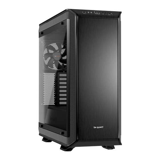
Página 35: Vista Detallada Y Descripción De Las Piezas
VISTA DETALLADA Y DESCRIPCIÓN DE LAS PIEZAS Ventana lateral de vidrio templado Panel de E/S frontal Tornillos de fijación Cuerpo de caja Jaula para unidades de disco óptico Filtro de aire de la base Jaula para discos duros Base de la caja Elemento de montaje de la fuente de Ventilador Silent Wings alimentación... -
Página 36: Puertos Multimedia Y De E/S Frontales
4.1 Puertos multimedia y de E/S frontales USB 3.0 USB 3.1 tipo C Gen. 2 Audio HD (micrófono y audio) Opción de carga rápida Botón de encendido Controlador de ventilador sin escalonamiento Interruptor de control LED Estación de carga Qi LED de disco duro 4.2 Puertos de E/S Los puertos de E/S frontales proporcionados requieren conexiones a su placa base. -
Página 37: Puertos Del Panel De La Placa De Circuito Impreso
4.3 Puertos del panel de la placa de circuito impreso Conector PWM a la placa base Conector PWM a los ventiladores Conector LED a la placa base Salida LED para LED externos adicionales Conector para los LED suministrados Conector para el cargador Qi Conector de alimentación SATA Conector de interruptor LED Cable de conexión para interruptor deslizante... -
Página 38: Instalación Y Manejo De Los Led
4.5 Instalación y manejo de los LED Es posible colocar libremente la iluminación LED suministrada, en caso de que se adapte a su sistema, mediante la fijación y conexión de las tiras adhesivas. Las tiras LED se deben conectar al conector «E» en el panel de la placa de circuitos impresos. Descripción de los LED La iluminación LED incluida en el suministro se puede controlar en varios modos de color y operación. El conector «D»... -
Página 67: Layouts
LAYOUTS LAYOUTS CONFIGURATIONS UKŁADY | CONFIGURACIONES | СХЕМЫ 配置 | 布局 | レイアウト УСТАНОВКИ | MOTHERBOARD: ATX MOTHERBOARD: E-ATX HDD slots facing the inside, space for a radiator in front HDD slots facing the outside, space for a large motherboard of the HDD cage | HDD-Slots der Innenseite zugewandt, | HHD-Slots der Außenseite zugewandt, Platz für großes Platz für Radiator vor dem HDD-Käfig | Emplacements... -
Página 70: Radiator Support
RADIATOR SUPPORT RADIATOREINBAU | SUPPORT RADIATEURS | WSPARCIE RADIATORÓW | SOPORTE DEL 散熱器支援 | 散热器支持 | ラジエーターのサポート RADIADOR | ПОДДЕРЖКА РАДИАТОРОВ | Position Size (mm) 120, 140, 180*, 240, 280, 360, 420 Front 120, 140, 240, 280, 360,420 Rear 120, 140 *Mounting point center to center: 154mm *Installationspunkt c/c liegt bei 154mm *Points de montage centre à... - Página 71 8.2 Removing the air filters | Entfernen der Luftfilter | Démontage des filtres a poussière | Wyciąganie filtrów powietrza | Retirada de los filtros de aire | Демонтаж воздушных фильтров | 拆除空氣濾網 | 卸下空气过滤器 | エアフィルターの取り外し EN: Draw out the lower filter and swing down the front filter. DE: Ziehen Sie den unteren und den vorderen Filter heraus. FR: Retirez le filtre inférieur et abaissez le filtre avant.
- Página 72 EN: Press all hooks on the inside of the case outwards, to release the front. DE: Drücken Sie alle Häkchen auf der Innenseite des Ge- häuses nach außen, um die Front zu lösen. FR: Appuyez sur tous les crochets depuis l’intérieur pour libérer la façade.
- Página 73 EN: Lift the cover up to remove it. DE: Heben Sie den Deckel an, um diesen zu entfernen. FR: Soulevez le panneau pour le retirer. PL: Podnieś pokrywę, aby ją wyjąć. ES: Levante la cubierta para retirarla. RU: Потяните панель вверх для ее снятия. TW: 向上抬起蓋板後取下。...
- Página 74 EN: Also unfasten the screws holding the PSU shroud on the front side. DE: Entfernen Sie die Schrauben im vorderen Bereich des PSU-Covers. FR: Dévissez également les vis qui retiennent le cache alimentation sur le côté avant. PL: Odkręć również śruby mocujące osłonę zasilacza na przedniej stronie.
- Página 75 EN: To remove the feet, unscrew their fastening screws and press them downwards and out. DE: Um die Gehäusefüße zu entfernen, lösen Sie die Schrauben und drücken die Standfüße nach unten heraus. FR: Pour retirer les pieds, dévissez les vis de fixation et enfoncez les vers le bas.
- Página 76 Pull the push-and-release kits out of the door. | Ziehen Fit these into the openings on the opposite side of the Sie die Push-and-Release-Kits aus der Tür. | Extraire door. | Stecken Sie diese nun wieder in die Öffnungen chaque système d’accroche de chaque côté de la porte. auf der anderen Seite der Tür.
-
Página 77: Affixing And Removing Disk Drives
8.8 Removing the ODD cage | Entfernen des ODD-Käfigs | Démontage cage lecteur optique | Wyjmowanie klatki ODD | Retirada de la jaula para unidades de disco óptico | Снятие корзины ODD | 拆除 ODD 盒 | 卸下光驱笼 | ODD ケージの取り外し EN: First remove the case front and the top cover. - Página 79 EN: It is possible to install two HDDs into the upper and lower parts of the double HDD cage. To secure these please use the screws supplied. DE: Es können zwei HDDs an der Ober- und Unterseite in einem doppelten HDD-Käfig installiert werden. Zur Befesti- gung benutzen Sie bitte die mitgelieferten Schrauben. FR: Il est possible d’installer deux disques durs dans les par- ties supérieure et inférieure de la cage double disque dur.
- Página 80 9.5 Installing an SSD on the PSU shroud | Installation einer SSD auf dem PSU-Cover | Installation d'un SSD sur le cache alimentation | Instalowanie dysku SSD na osłonie zasilacza | Instalación de un SSD Установка SSD на кожух БП | 將 SSD 安裝在 PSU 護罩上 en la cubierta de la fuente de alimentación | | 在电源护罩上安装固态硬盘...
- Página 81 9.6 HDD slot cover | HDD-Slot Cover | Couverture de fente pour disque dur | Osłona gniazda HDD | Cubier- Заглушка слотов HDD | HDD 插槽蓋板 | 硬盘插槽盖 | HDD スロッ トカバー ta de la ranura para disco duro | EN: The five HDD slot covers may each be positioned in three ways.
-
Página 82: Modifying The Case Layout
Warning: Any segments that are snapped off cannot be refitted. Warnung: Einmal herausgebrochene Segmente können nicht wieder angebracht werden. Attention: Les segments cassés ne peuvent pas être réaménagés. Ostrzeżenie: żadnych odłamanych segmentów nie można ponownie zamocować. Advertencia: Los segmentos desprendidos no se pueden volver a montar. Внимание: Удаленные сегменты не могут быть восстановлены. 警告: 任何折斷的部分無法重新裝回。 警告:片段去掉后无法再重新装回。... - Página 83 EN: If you wish, you can now use the motherboard tray as a test bench. DE: Das Mainboard-Tray kann nun optional als Test-Bench genutzt werden. FR: Si vous le souhaitez, vous pouvez maintenant utiliser le plateau de la carte mère comme table de test. PL: Jeśli chcesz, możesz teraz używać tacki płyty głównej jako stanowiska testowego (test bench). ES: Si lo desea, puede utilizar ahora la bandeja de la placa base como banco de pruebas.
- Página 84 EN: Reposition the covers on the rear side, so that that they fill any gaps and secure the covers with screws. DE: Positionieren Sie die rückseitigen Abdeckungen neu, um die Lücke zu schließen und befestigen Sie die Abdeck- ung mit Schrauben. FR: Repositionnez les caches sur le côté arrière, de sorte qu’ils remplissent les et fixez les couvercles avec des vis.
- Página 85 EN: Detach the HDD panel by unscrewing its ten screws. DE: Lösen Sie das HDD-Panel ab, indem Sie die zehn Schrauben lösen. FR: Détachez le panneau du disque dur en dévissant ses dix vis. PL: Zdejmij panel HDD odkręcając jego dziesięć śrub. ES: Separe el panel de disco duro desenroscando sus diez tornillos.
- Página 86 10.3 Mounting positions for the power supply | Einbaupositionen für das Netzteil | Positions de montage de l'alimentation | Położenia montażowe zasilacza | Posiciones de montaje para la fuente de Размещение блока питания | 電源供應器安裝位置。 | 电源的安装位置 | 電源装置の取り alimentación | 付け位置...
- Página 87 EN: Fixing points of the step screws for inverted layout. DE: Befestigungspunkte der Step-Schrauben für invertierten Einbau. FR: Points de fixation des vis pour la disposition inversée. PL: Punkty mocowania śrub krokowych dla układu odwróconego. ES: Puntos de fijación de los tornillos de estrella para la configuración invertida. RU: Монтажные точки крепления для обратного расположения. TW: 反向配置時圓頭螺絲的固定點。 CN: 倒置布局的台阶螺丝固定点。 JP: 反転レイアウト用の段付ねじの固定ポイント。 EN: Affix the PSU mounting at the desired layout depth. DE: Befestigen sie die PSU-Halterung entsprechend der gewählten Einbautiefe.
- Página 88 10.4 Assembling with inverted layout | Zusammenbau eines inversen Aufbaus | Assemblage avec disposition inversée | Montaż w układzie odwróconym | Montaje con configuración invertida | Сборка корпуса с обратной компоновкой | 反向配置組裝 | 倒置布局组装 | 反転レイアウトでの組立 EN: To install the system on the opposite side of the case, the motherboard tray, HDD panel, PSU shroud and the PSU mounting must all be relocated.
-
Página 89: Installing The Components
EN: Now reinstall the PSU shroud and the motherboard tray. DE: Installieren sie nun das PSU-Cover und das Main- board-Tray. FR: Maintenant, réinstallez le cache alimentation et le pla- teau de la carte mère. PL: Teraz ponownie zainstaluj osłonę zasilacza i tackę płyty głównej. ES: Ahora, reinstale la cubierta de la fuente de ali- mentación y la bandeja de la placa base. - Página 90 11.2 Installing the power supply | Installation des Netzteils | Installation de l'alimentation | Instalacja | 安裝電源供應器 | zasilacza | Instalación de la fuente de alimentación | Установка блока питания 安装电源 | 電源装置の取り付け EN: As a first step, remove the PSU shroud. Next unscrew the screws holding the PSU mounting and detach this. DE: Im ersten Schritt entfernen Sie das PSU-Cover.
- Página 91 EN: Fit the power cable into the rear of the PSU before posi- tioning the PSU and mounting in the case. Then secure the PSU mounting with its screws. DE: Bevor Sie die PSU-Halterung in Position bringen, schließen Sie das Netzkabel an das Netzteil an. Sichern Sie abschließend die Netzteilhalterung am Gehäuse mit Hilfe der Schrauben.
- Página 92 11.4 Possibilities for liquid cooling | Möglichkeiten für die Wasserkühlung | Possibilités de refroidissement liquide | Możliwości chłodzenia cieczą | Posibilidades de refrigeración por líquido | Установка системы водяного охлаждения | 液體冷卻的可能性 | 液体冷却的可能性 | 液体冷却の可能性 EN: Attach the pump to the LCS bracket provided. To decouple the pump for sound, use the rubber grommets supplied (nuts and bolts are not included).