LiftMaster 045DCT Guia De Inicio Rapido
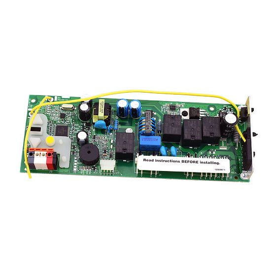
Reemplazo de la tarjeta logica del receptor
Tabla de contenido
Idiomas disponibles
Idiomas disponibles
Enlaces rápidos
Installation
1
Before you begin
To prevent possible SERIOUS INJURY or
DEATH:
• Disconnect ALL electric and battery
power BEFORE performing ANY service
or maintenance.
To prevent damage to the receiver/logic
board, DO NOT touch printed circuit board
of replacement receiver/logic board during
installation.
ALWAYS wear protective gloves and eye
protection when changing the battery or
working around the battery compartment.
2
Remove the receiver logic board
2.1 Disconnect the wires from the quick-connect terminals (A).
Remove the receiver logic board end panel from the garage
door opener.
A
To insert or remove
the wires from the
terminal, push in the
tab with a
screwdriver tip.
NOTE: The products illustrated in the instructions are for reference. Your product may look different.
1.1 Remove the light lens by pulling the top
sides of the light lens and rotate the light
lens down. Squeeze the light lens clips to
remove lens from end panel.
2.2 Unplug the wire harnesses from the receiver logic
board. You may need needle-nosed pliers, to
remove the harnesses.
RECEIVER LOGIC BOARD REPLACEMENT
1.2 To maintain your warranty, place the
provided label over the existing label on
the end panel of the garage door opener.
2.3 Remove the receiver
1
Models 045DCT and 045DCT125
1.3 Disconnect electrical and battery power
(if applicable) to the garage door opener.
.
logic board from the
end panel by removing
the 2 screws and
releasing the 2 clips.
Clips
Screws
Tabla de contenido

Manuales relacionados para LiftMaster 045DCT


Resumen de contenidos para LiftMaster 045DCT
-
Página 9: Desconecte Los Cables De Los Terminales De Conexión
REEMPLAZO DE LA TARJETA LÓGICA DEL RECEPTOR Modelos 045DCT y 045DCT125 Installation Antes de comenzar NOTA: Los productos ilustrados en las instrucciones son para su referencia. Su producto puede verse diferente. 1.2 A fi n de conservar su garantía, 1.3 Desconecte del abre-puertas de 1.1 Retire la lente de luz tirando de los... -
Página 10: Instale La Nueva Tarjeta Lógica Del Receptor
Instale la nueva tarjeta lógica del receptor 3.1 Conecte el hato de cables a la nueva 3.2 Inserte los cables de la antena a través 3.3 Vuelva a insertar los cables. 3.4 Instale la lente de luz alineándola de los orifi cios del panel posterior. tarjeta lógica del receptor. -
Página 11: Programación De La Carrera
Ajustes Programación de la carrera 1.1 Oprima y mantenga oprimido el 1.2 Oprima y mantenga oprimido el 1.3 Una vez que la puerta esté en la botón “Ajuste” hasta que el botón botón ARRIBA hasta que la puerta posición deseada, oprima y suelte el ARRIBA empiece a parpadear y/o se encuentre en la posición Botón “Ajuste”. -
Página 12: Prueba Del Sistema De Seguridad De Reversa
Prueba del sistema de seguridad de reversa Si la puerta se detiene y no retrocede al 2.1 Con la puerta completamente abierta, 2.2 Oprima el botón pulsador del control hacer contacto con la obstrucción, aumente coloque una tabla de 3,8 cm remoto para cerrar la puerta.