Tabla de contenido
-
-
-
-
-
-
-
-
-
-
-
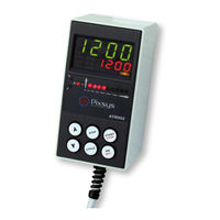
Displays and Keys Function
9
-
Numeric Indicators (Display)
10
-
Meaning of Status Lights (Led)
10
-
-
Programming and Configuration
12
-
Programming (or Modifying) Cycle Data
12
-
Programming of the Step (Segment)
13
-
Programming of the Alarm/Auxiliary (if Configured)
13
-
-
-
Start of a Cycle and Setting of Delayed Start
14
-
Fast Advancement Function
14
-
Simple Controller Function
15
-
-
-
-
-
Recovery of Interrupted Cycle
16
-
Recovery with Automatic Gradient
16
-
-
Loading Default Values
18
-
Configuration for Installer
19
-
Table of Confi Guration Parameters
20
-
-
-
-
-
-
Ui.D.2 Visualization Display
21
-
-
2Nd Level Parameters (for Expert Operators)
24
-
Alarm Intervention Modes
26
-
Band Alarm (Setpoint-Process)
27
-
Table of Anomaly Signals
28
-
-
Identificazione del Modello
32
-
-
Caratteristiche Generali
32
-
Caratteristiche Hardware
33
-
Caratteristiche Software
33
-
Dimensioni E Installazione
33
-
Collegamenti Elettrici
34
-
Schema DI Collegamento
34
-
Funzione Dei Visualizzatori E Tasti
34
-
Indicatori Numerici (Display)
35
-
Significato Delle Spie DI Stato (Led)
35
-
-
Programmazione E Configurazione
36
-
Programmazione (O Modifica) Dati DI un Ciclo
37
-
Programmazione Dello Step (Spezzata/Passo)
37
-
Programmazione Dell'allarme/ Ausiliario (se Configurato)
38
-
-
Partenza DI un Ciclo DI Lavoro
38
-
Partenza DI un Ciclo E Impostazione Partenza Ritardata
38
-
Funzione Avanzamento Veloce
39
-
Funzione Regolatore Semplice
39
-
Funzioni del Programmatore
40
-
-
-
-
Recupero Ciclo Interrotto
41
-
Recupero con Gradiente Automatico
41
-
Recupero con Gradiente Impostabile
42
-
-
Caricamento Valori DI Default
43
-
Configurazione Per Installatore
43
-
Tabella Parametri DI Configurazione
44
-
Parametri DI 1° Livello
44
-
-
O.cal. Offset Calibration
44
-
-
Up.l.s. Upper Limit Setpoint
45
-
-
-
-
S.D.tu. Setpoint Deviation Tune
45
-
C. HY. Command Hysteresis
45
-
-
-
-
-
13 C. S.e. Command State Error
46
-
Ui.D.2 Visualization Display
46
-
-
Sp.fu. Special Functions
46
-
-
Cy.au. Cycles Available
46
-
-
21 M.g.s.e. Max. Gap Step End
47
-
22 R. I .Cy. Recovery Interrupted Cycle
47
-
-
Parametri DI 2° Livello (Per Operatori Esperti)
48
-
24 A. 1 .S.o. Alarm 1 State Output
48
-
.Th. Alarm 1 Threshold
48
-
26 A. 1 .Hy. Alarm 1 Hysteresis
48
-
27 A. 1 .Se. Alarm 1 State Error
48
-
28 A. 1 .Ld. Alarm 1 Led
48
-
29 A. 1 .A.t. Alarm 1 Action Type
48
-
40 C.flt. Conversion Filter
48
-
41 S.spu. Starting Setpoint
48
-
-
-
Pow.C. Power Consumption
49
-
-
Cy. 1 .N. Cycle 1 Name
49
-
Modalità DI Funzionamento Allarme
51
-
Allarme Indipendente Correlato al Setpoint
52
-
Tabella Segnalazioni Anomalie
52
-
-
Identification du Modèle
56
-
-
Caractéristiques Générales
56
-
Caractéristiques Hardware
57
-
Caractéristiques Software
57
-
Dimensions et Installations
57
-
Connexions Électriques
58
-
-
Visualisation Façade Avant et Fonctionnalité des Touches
58
-
Indicateurs Numeriques (Affichages)
59
-
-
-
Programmation et Configuration
61
-
Programmation (ou Modification) Données du Cycle
61
-
Programmation du Step (Segment)
62
-
Programmation de L'alarme/Auxiliaire (si Configuré)
62
-
-
Départ D'un Cycle de Travail
63
-
Départ D'un Cycle et Sélection du Départ Différé
63
-
Fonction Avancement Rapide
63
-
Fonction Régulateur Simple
64
-
Fonctions du Programmateur
64
-
-
-
-
Récupération du Cycle Interrompu
65
-
Récupération Avec Gradient Automatique
66
-
Récupération Avec Gradient Sélectionnable
66
-
Attente Fin du Segment
67
-
Chargement des Valeurs Par Défaut
67
-
Configuration pour L'installateur
68
-
Tableau des Paramètres de Configuration
69
-
Paramètres de Premier Niveau
69
-
-
O.cal. Offset Calibration
69
-
Up.l.s. Upper Limit Setpoint
69
-
-
-
-
S.D.tu. Setpoint Deviation Tune
69
-
C. HY. Command Hysteresis
70
-
-
10 T. I . Integral Time
70
-
11 T.D. Derivative Time
70
-
-
13 C. S.e. Command State Error
70
-
Ui.D.2 Visualization Display
70
-
-
Sp.fu. Special Functions
71
-
-
Cy.au. Cycles Available
71
-
-
-
.S.o. Alarm 1 State Output
72
-
27 A. 1 .Se. Alarm 1 State Error
72
-
Paramètres de Deuxième Niveau (pour Operateurs Experts)
73
-
-
Pow.C. Power Consumption
73
-
-
-
Modalités D'intervention de L'alarme
75
-
Alarme de Bande (Point de Consigne-Procès)
76
-
-
Alarme Indépendante Liée au Point de Consigne
76
-
-
-
-
-
-
-
-
-
-
-
-
-
-
-
-
-
-
-
-
-
-
-
-
-
-
-
-
-
-
-
-
-
-
-
-
-
-
-
-
-
-
-
-
-
-
-
-
-
-
-
-
-
-
-
-
-
-
-
-
-
-
-
-
-
-
Kennzeichnung des Modells
106
-
-
-
Hardware-Eigenschaften
107
-
Software-Eigenschaften
107
-
Abmessungen und Installation
107
-
Elektrische Anschlüsse
108
-
-
Funktion der Anzeigen und Tasten
108
-
Nummernanzeige (Display)
109
-
Bedeutung der Statusleuchten (LED)
109
-
-
Programmierung und Konfiguration
110
-
Programmierung (oder Änderung) Daten eines Zyklus
111
-
Programmierung des Steps (Segments/Schritts)
111
-
Programmierung Alarm/Hilfsausgang (wenn Konfiguriert)
112
-
-
-
Start eines Zyklus und Einstellung der Startverzögerung
113
-
Schnelle Vorstell-Funktion
113
-
Einfache Reglerfunktion
114
-
Funktionen des Programmiergeräts
114
-
-
Automatischer Abgleich (Selbstoptimierung/Autotuning)
115
-
-
Wiederaufnahme Unterbrochener Zyklus
115
-
Wiederaufnahme mit Automatischer Rampe
116
-
Wiederaufnahme mit Einstellbarer Rampe
116
-
Wartezeit an Step-Ende
117
-
Laden der Default-Werte
117
-
Konfiguration für den Installateur
118
-
Tabelle der Konfigurationsparameter
119
-
-
-
-
-
-
-
-
-
13 C. S.e. Command State Error
120
-
Ui.D.2 Visualization Display
120
-
Sp.fu. Special Functions
121
-
-
Cy.au. Cycles Available
121
-
Waiting Time Step End
121
-
-
24 A. 1 .S.o. Alarm 1 State Output
122
-
25 A. 1 .Th. Alarm 1 Threshold
122
-
27 A. 1 .Se. Alarm 1 State Error
122
-
Parameter 2. Stufe (für Erfahrene Bediener)
123
-
-
-
Pow.C. Power Consumption
124
-
-
-
-
