Bosch Start Line TCE 420 Manuales
Manuales y guías de usuario para Bosch Start Line TCE 420. Tenemos 2 Bosch Start Line TCE 420 manuales disponible para descarga gratuita en PDF: Manual Original, Instructions De Réparation
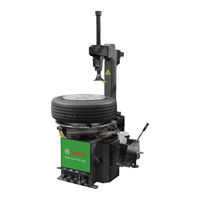
Bosch Start Line TCE 420 Manual Original (144 páginas)
Marca: Bosch
|
Categoría: Equipo Industrial
| Tamaño: 3 MB
Tabla de contenido
-
Deutsch
4-
Tabla de Contenido4
-
1 Verwendete Symbolik
5-
In der Dokumentation5
-
Warnhinweise - Aufbau und Bedeutung5
-
Symbole - Benennung und Bedeutung5
-
-
Auf dem Produkt5
-
Warnung5
-
-
2 Benutzerhinweise
6-
Allgemeine Bestimmungen6
-
Einsatzbereich6
-
Anforderungen und Hinweise zur Betriebssicherheit7
-
-
3 Produktbeschreibung
8-
Bestimmungsgemäße Verwendung8
-
Typenschild8
-
Gerätebeschreibung8
-
Lieferumfang9
-
-
4 Transport
9-
Transport und Verpackung9
-
Transportmethode9
-
-
5 Auspacken
9-
TCE 420 Aufstellen9
-
-
6 Erstinbetriebnahme
11-
TCE 420 Befestigen12
-
TCE 420 an Strom- und Druckluftversorgung Anschließen12
-
Pedalfunktionen Prüfen12
-
-
7 Bedienung
13-
Sicherheitshinweis13
-
Vor dem Betrieb Prüfen13
-
Hinweise zu Besonderen Felgen und Reifen13
-
Abdrücken der Reifenwulst14
-
Ausrichtung der Felge15
-
Einspannen der Felge16
-
Spannen der Felge von Außen16
-
Spannen der Felge von Innen16
-
-
Reifen Demontieren16
-
Montagekopf Positionieren17
-
Oberen Wulst über das Felgenhorn Hebeln17
-
Oberen Wulst Demontieren18
-
Unteren Wulst Demontieren (mit Montagekopf)18
-
Räder Abnehmen18
-
-
Reifen Montieren18
-
7.8.1 Auswahl des Reifens19
-
Reifen Vorbereiten19
-
7.8.3 Montagekopf Positionieren19
-
Unteren Wulst Montieren19
-
7.8.5 Oberen Wulst Montieren19
-
-
7.9 Ablauf der Montage/Demontage bei Leichtmetallfelgen20
-
-
8 Befüllen
20-
8.1 Befüllung von Schlauchlosreifen21
-
Befüllung von Reifen mit Schläuchen21
-
-
9 Wartung
22-
9.2.1 Wartungseinheit und22
-
-
10 Hinweise bei Störungen
24 -
11 Außerbetriebnahme
25-
Ortswechsel25
-
Vorübergehende Stilllegung25
-
Entsorgung und Verschrottung25
-
Wassergefährdende Stoffe25
-
TCE 420 und Zubehör25
-
-
-
12 Technische Parameter
26-
Abmessungen26
-
Einsatzbereich26
-
Drehtellertyp26
-
Abdrückschaufel26
-
Leistung26
-
Pneumatik-Schaltbild26
-
-
-
English
27-
1 Symbols Used
28-
In the Documentation28
-
Warning Notices - Structure and Meaning28
-
Symbols in this Documentation28
-
-
On the Product28
-
Warning28
-
-
2 User Instructions
29-
General Provision29
-
Range of Application29
-
Safety Requirements and Notes30
-
-
3 Product Description
31-
Intended Use31
-
Machine Rating Plate31
-
Device Description31
-
-
4 Transport
32-
Transport and Packing32
-
Transport Method32
-
-
5 Unpacking
32-
Setting up the TCE32
-
Scope of Delivery32
-
-
6 Initial Commissioning
34-
Fastening the TCE 42035
-
Connecting the TCE 420 to Power and the35
-
Checking the Pedal Functions35
-
-
7 Operation
36-
Safety Notice36
-
Check before Use36
-
Information about Special Rims and Tires36
-
Unseating the Tire Bead37
-
Rim Location Direction38
-
Clamping the Rim39
-
Clapping the Rim from the Outside39
-
Clamping the Rim from the Inside39
-
-
Demounting the Tire39
-
Positioning of the Mounting Head40
-
Lever the Top Bead over the Rim Flange40
-
Demounting the Top Bead41
-
Demounting the Bottom Bead (with the Aid of the Mounting Head)41
-
Removing Wheels41
-
-
Mounting the Tire41
-
28 7.8.1 Selecting the Tire42
-
Preparing the Tire42
-
28 7.8.3 Positioning of the Mounting Head42
-
28 7.8.4 Mounting the Lower Tire Bead42
-
28 7.8.5 Mounting the Top Bead42
-
-
28 7.9 Procedure for Mounting/Demounting Alloy Rims43
-
29 8.1 Inflating Tubeless Tires44
-
29 8.2 Inflating Tubed Tires44
-
-
9 Maintenance
45-
31 9.2 Maintenance Operations45
-
Maintenance Unit and Bead Breaking Cylinder Belt45
-
-
-
10 Troubleshooting
47 -
11 Decommissioning
48-
Change of Location48
-
Temporary Shutdown48
-
Disposal and Scrapping48
-
Substances Hazardous to Water48
-
TCE 420 and Accessories48
-
-
-
12 Technical Parameter
49-
Dimensions for49
-
Range of Application49
-
Turntable Type49
-
Bead Breaker Blade49
-
Power49
-
Pneumatic Diagram49
-
-
-
Français
50-
1 Symboles Utilisés
51-
Dans la Documentation51
-
Avertissements - Conception et Signification51
-
Symboles - Désignation51
-
Et Signification XXX51
-
-
-
Sur le Produit51
-
Avertissement51
-
-
2 Consignes Utilisateur
52-
Dispositions Générales52
-
Domaine D'application52
-
Exigences et Remarques Relatives à la Sécurité D'exploitation53
-
-
3 Description du Produit
54-
Utilisation Conforme54
-
Plaque Signalétique54
-
Description de L'appareil54
-
Contenu de la Livraison55
-
-
4 Transport
55-
Transport et Emballage55
-
Méthode de Transport55
-
-
5 Déballage
55-
Installation du TCE55
-
-
6 Première Mise en Service
57-
Fixer le TCE58
-
Raccordement du TCE 420 au Courant Électrique et à L'alimentation en Air Comprimé58
-
Contrôle des Fonctions de Pédales58
-
-
7 Utilisation
59-
Consigne de Sécurité59
-
Contrôler Avant Utilisation59
-
Remarques Relatives à des Jantes et Pneumatiques Particuliers59
-
Détalonnage du Talon de Pneumatique60
-
Ajustage de la Jante61
-
Serrage de la Jante62
-
Serrage de la Jante de L'extérieur62
-
Serrage de la Jante de L'intérieur62
-
-
Démonter les Pneumatiques62
-
Positionnement de la Tête de Montage63
-
Faire Levier pour Passer le Talon Supérieur63
-
Au-Dessus du Bord de la Jante63
-
-
Démontage du Talon Supérieur64
-
Démontage du Talon Inférieur (Avec la Tête de Montage)64
-
Retrait des Roues64
-
-
Montage des Pneumatiques64
-
51 7.8.1 Sélection du Pneumatique65
-
Préparation du Pneumatique65
-
51 7.8.3 Positionnement de la Tête de Montage65
-
Montage du Talon de Pneumatique65
-
-
Déroulement du Montage/Démontage pour des Jantes en Alliage Léger66
-
-
8 Gonflage
66-
Gonflage de Pneumatiques Sans Chambre à Air67
-
53 8.2 Gonflage de Pneumatiques Avec Chambres à67
-
54 9.2 Etapes de Maintenance68
-
55 9.2.1 Conditionneur et Vérin Pousseur68
-
Courroies69
-
-
-
10 Remarques en cas de Dysfonctionnements
70 -
11 Mise Hors Service
71-
Déplacement71
-
Mise Hors Service Provisoire71
-
Elimination et Mise au Rebut71
-
Substances Dangereuses71
-
Pour les Eaux XXX71
-
11.3.2 TCE 420 et Accessoires71
-
-
-
12 Paramètres Techniques
72-
Dimensions72
-
Domaine D'application72
-
Type de Plateau de Rotation72
-
Pale de Compression72
-
Puissance72
-
Schéma des Connexions Pneumatiques72
-
Dimensiones95
-
Simboli Utilizzati97
-
Nella Documentazione97
-
Indicazioni DI Avvertimento - Struttura E Significato97
-
Sul Prodotto97
-
Simboli Nella Presente97
-
Istruzioni Per L'utente98
-
Norme Generali98
-
Campo D'impiego98
-
Descrizione del Prodotto100
-
Impiego Previsto100
-
Targhetta DI Identificazione100
-
Descrizione del Dispositivo100
-
Trasporto E Imballaggio101
-
Sistema DI Trasporto101
-
Prima Messa in Esercizio103
-
Orientamento del Cerchio107
-
Sollevare Il Tallone Superiore Oltre Il Bordo del Cerchio109
-
Montaggio Dello Pneumatico110
-
Interventi DI Manutenzione114
-
Cambio DI Ubicazione117
-
Messa Fuori Servizio Temporanea117
-
Smaltimento E Rottamazione117
-
Parametri Tecnici118
-
Schema Pneumatico118
-
Símbolos Utilizados120
-
Instruções de Utilização121
-
Disposições Gerais121
-
Campo de Aplicação121
-
Requisitos E Avisos sobre a Segurança Operacional122
-
Descrição Do Produto123
-
Utilização Adequada123
-
Descrição Do Aparelho123
-
Volume de Fornecimento124
-
Transporte E Embalagem124
-
Primeira Colocação Em Funcionamento126
-
Instruções de Segurança128
-
Avisos para Aros E Pneus Especiais128
-
Processo de Montagem/Desmontagem Em Aros de Metal Leve135
-
Enchimento de Pneus Sem Mangueira136
-
Enchimento de Pneus Com Mangueiras136
-
Manutenção137
-
Mudança de Local140
-
TCE 420 E Acessórios140
-
Colocação Temporária Fora de Serviço140
-
Eliminação E Transformação Em Sucata140
-
Substâncias Poluentes para a Água140
-
Parâmetros Técnicos141
-
Esquema Do Sistema Pneumático141
-
Tipo de Prato Giratório141
-
-

Bosch Start Line TCE 420 Instructions De Réparation (82 páginas)
Máquinas montaneumáticos
Marca: Bosch
|
Categoría: Cambiadores de Llanta
| Tamaño: 1 MB
Tabla de contenido
-
Deutsch
4-
Tabla de Contenido4
-
1 Verwendete Symbolik
5-
In der Dokumentation5
-
Warnhinweise - Aufbau und Bedeutung5
-
Symbole - Benennung und Bedeutung5
-
-
Auf dem Produkt5
-
-
2 Allgemeine Hinweise
5 -
3 Regelmäßige Wartung
6-
Verwendung und Wartung des Druckluftreglers6
-
Muttern an Gerät in Regelmäßigen Zeitabständen7
-
Dämpfer an den Pedalventilen in Regelmäßigen Zeitabständen Reinigen7
-
-
4 Einrichtung des Geräts
8-
Winkel des Montagekopfes Einstellen8
-
Sechskant-Sicherungsplatte Justieren8
-
Vierkant-Sicherungsplatte Justieren8
-
Vierkantwellenrolle Justieren8
-
Feststellschrauben und -Muttern Unten am Schwenkarm Justieren9
-
Stellung der Pedalventilstange des Wulstabdrückzylinders Einstellen9
-
Stellung der Pedalventilstange des Drehtellerzylinders Einstellen9
-
Stellung der Pedalventilstange des Schwenkzylinders Einstellen9
-
Dämpfer Oben am Schwenkzylinderventil Einstellen10
-
Stellung der Spannklauen Justieren10
-
Sicherungslasche des Wulstabdrückzylinders Justieren11
-
Motorriemen Einstellen11
-
Stellung des Schalters Justieren11
-
-
5 Austausch von Komponenten
12-
Drehtellerzylinder und Dichtungsringe Austauschen12
-
Drehtellerzylinder Austauschen12
-
Äußere Dichtungsringe Ersetzen12
-
Innere Dichtungsringe Ersetzen12
-
-
Wulstabdrückzylinder und Dichtungsringe Ersetzen12
-
Wulstabdrückzylinder Wechseln12
-
-
Schwenkzylinder und Dichtungsringe Austauschen13
-
Schwenkzylinder Austauschen13
-
Dichtungsringe IM Zylinder Ersetzen13
-
-
5.4 Sperrzylinder und Dichtungsringe der13
-
Sechskantwelle Ersetzen13
-
-
Sperrzylinder und Dichtungsringe der Vierkantwelle Ersetzen13
-
5.6 Ventilgriff und Dichtungsringe Ersetzen13
-
Luftverteiler und Dichtungsringe Ersetzen14
-
5.8 Pedalventilbaugruppe und Dichtungsringe Ersetzen14
-
5.9 Auslassventil und Dichtungsringe Ersetzen14
-
Auslassventil Ersetzen14
-
Dichtungsringe Ersetzen14
-
-
Getriebe Ersetzen14
-
Schalter Wechseln15
-
Kondensator Austauschen15
-
Motor Austauschen15
-
5.14 Pedalspannfeder oder Torsionsfeder Ersetzen15
-
-
6 Fehlersuche und -Behebung
16-
6.1 Drehteller Dreht sich nicht16
-
6.2 Schwaches Drehmoment des Drehtellers16
-
Spannklauen Bewegen sich nicht oder nicht16
-
Spannklauen Bewegen sich von selbst17
-
6.5 Spannklauen können die Felge nicht Festhalten17
-
Montagekopf Verschleißt zu Schnell17
-
6.7 Stellung des Montagekopfes nach der Rückkehr17
-
6.8 Zylinder Undicht17
-
Getriebe Dreht sich nicht oder unter Großer17
-
Unregelmäßige Auf- und Abbewegung der Sechskantwelle17
-
11 6.11 Pedal Kehrt nicht Zurück17
-
11 6.12 Schwenkarm Bewegt sich nicht oder zu18
-
Langsam18
-
-
Wulstabdrückschaufel Bewegt sich zu Langsam18
-
12 6.14 Wulstabdrückung ohne Kraft18
-
-
7 Umgang mit Öl
19 -
8 Übersichtsschaltplan Pneumatik
20
-
-
English
24-
1 Symbols Used
25-
In the Documentation25
-
Warning Notices - Structure and Meaning25
-
Symbols in this Documentation25
-
-
On the Product25
-
-
2 General Principles
25 -
3 Maintenance Routine
26-
Air Regulator Usage and Maintain26
-
Tighten the Nuts on Equipment at Regular Intervals27
-
Clean the Silencer on Pedal Valves at Regular Intervals27
-
-
4 Equipment Adjustment
28-
Adjust the Angle of Demounting Head28
-
Adjust the Hex Locking Plate28
-
Adjust the Square Locking Plate28
-
Adjust the Square Shaft Roller28
-
Adjust Fixing Bolts and Nuts at the Lower End of Tilt Arm29
-
Adjust the Position of Pedal Valve Rod for Bead Break Cylinder29
-
Adjust the Position of Pedal Valve Rod for Turntable Cylinder29
-
Adjust the Position of Pedal Valve Rod for Tilt Cylinder29
-
Adjust the Silencer at Top of Tilt Cylinder Valve30
-
Adjust the Position of Clamps30
-
Adjust the Fixing Sleeve of Bead Break Cylinder31
-
Adjust the Motor Belt31
-
Adjust the Position of Switch31
-
-
5 Change the Components
32-
Change Turntable Cylinder and Sealing Rings32
-
Change Turntable Cylinder32
-
Change Outside Sealing Rings32
-
Change Inside Sealing Rings32
-
-
Change Bead Break Cylinder and Sealing Rings32
-
Change Bead Break Cylinder32
-
-
Change Tilt Cylinder and Sealing Rings33
-
Change Tilt Cylinder33
-
Change the Sealing Rings in Cylinder33
-
-
Change Hex Shaft Locking Cylinder and Sealing Rings33
-
25 5.5 Change Square Shaft Locking Cylinder and33
-
Sealing Rings33
-
-
Change the Handle Valve and Sealing Rings33
-
Change Exhaust Valve and Sealing Rings34
-
25 5.9.1 Change the Exhaust Valve34
-
Change Sealing Rings34
-
-
Change Gearbox34
-
Change the Switch35
-
Change the Capacitor35
-
Change Motor35
-
Change the Pedal Tension Spring or Torsion Spring35
-
-
6 Trouble
36-
28 6.1 Turntable Not Rotate36
-
28 6.2 Powerless Turntable Torsion Power36
-
28 6.3 Clamps Not Move or Moves Not Smoothly36
-
28 6.4 the Clamps Move Automatically37
-
The Clamps Cannot Fix the Rim37
-
29 6.6 Demounting Head Is Wear and Tear too Fast37
-
The Position of Demounting Head Has Change37
-
Leakage in Cylinder37
-
29 6.9 the Gearbox Not Rotate or Has Big Noise37
-
Hex Shaft Moves up and down Not Smoothly37
-
Pedal Cannot Return Back37
-
Tilt Arm Cannot Tilt or Tilt Slowly37
-
Bead Break Blade Moves Slowly38
-
Powerless Bead Break Power38
-
-
7 Oil Usage
38 -
8 Pneumatic Schematic Dia- Gram
39 -
9 Circuit Diagram
40-
Simboli Utilizzati63
-
Nella Documentazione63
-
Sul Prodotto63
-
Avvertenze Generali63
-
Manutenzione Regolare64
-
Pulire Gli Ammortizzatori Sulle Valvole del Pedale a Intervalli Regolari65
-
Impostare la Cinghia del Motore69
-
Sostituzione Dei Componenti70
-
Il Piatto Rotante Non Gira74
-
Coppia Debole del Piatto Rotante74
-
Il Braccio Orientabile Non Ruota O Ruota Troppo Lentamente76
-
La Paletta Dello Stallonatore si Muove Troppo Lentamente76
-
Schema Elettrico79
-