Bosch EPS 625 Manuales
Manuales y guías de usuario para Bosch EPS 625. Tenemos 2 Bosch EPS 625 manuales disponible para descarga gratuita en PDF: Manual Original

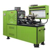
Bosch EPS 625 Manual Original (462 páginas)
Marca: Bosch
|
Categoría: Bombas de Agua
| Tamaño: 60 MB
Tabla de contenido
-
Deutsch
4-
Contents English3
-
Tabla de Contenido4
-
1 Verwendete Symbolik
6-
In der Dokumentation6
-
Warnhinweise - Aufbau und Bedeutung6
-
Symbole - Benennung und Bedeutung6
-
-
Auf dem Produkt6
-
-
2 Benutzerhinweise
7-
Wichtige Hinweise7
-
Sicherheitshinweise7
-
Elektromagnetische Verträglichkeit (EMV)7
-
-
3 Produktbeschreibung
8-
Bestimmungsgemäße Verwendung8
-
Voraussetzungen8
-
Lieferumfang8
-
Sonderzubehör9
-
Gerätebeschreibung9
-
Eps9
-
Antrieb10
-
Vorderseite10
-
Prüfstandsrahmen10
-
Messglasträger (MGT)11
-
Schaltschrank12
-
Anzeige- und Bedieneinheit13
-
Druckluftregler14
-
Prüfölversorgung15
-
Druckregelventil für Hoch- und Niederdruck15
-
Schmierölversorgung (Sonderzubehör)15
-
-
Prüföltank16
-
Prüfölkühlung16
-
Prüfölheizung16
-
-
Temperaturmessung und -Regelung17
-
Temperaturregelung für VE-Pumpen17
-
Spannungsversorgung für Start-/Stoppventil (für Verteilerpumpen)17
-
-
4 Inbetriebnahme
18-
Transport18
-
EPS 625 Auspacken18
-
EPS 625 zum Installationsort Transportieren18
-
Vor dem Ersten Einschalten19
-
Installation19
-
Netzanschlüsse20
-
Anschluss einer Zusätzlichen Spannungsversorgung21
-
Anzeige- und Bedieneinheit Anschließen22
-
Prüfölanschlüsse23
-
Kühlwasseranschluss24
-
Manometer Kontrollieren24
-
-
-
5 Programmbeschreibung
25-
5.1 Anzeige- und Bedieneinheit - Bedientasten25
-
Anzeige- und Bedieneinheit25
-
Bildschirmanzeige25
-
-
Sollwerte Ändern26
-
5.3.1 Motordrehzahl Einstellen26
-
5.3.2 Drehrichtung Ändern26
-
5.3.3 Anzahl der Hübe Einstellen26
-
-
Auswahl von Voreingestellte Hubzahl27
-
Und Motordrehzahl27
-
5.4.1 Wählen einer Voreingestellten Hubzahl27
-
5.4.2 Voreingestellte Drehzahl Wählen27
-
-
5.5 Kundenspezifische Drehzahlsätze Speichern27
-
5.6 Hubzählung Aktivieren27
-
-
6 Betrieb
28-
10 6.3 Not-Aus-Schalter28
-
11 6.3.1 Aktivieren des Not-Aus-Schalters28
-
12 6.3.2 Deaktivieren des Not-Aus-Schalters28
-
-
13 6.4 Vorbereitung der Prüfung29
-
14 6.5 Prüfen von Vorhub, Förderbeginn und30
-
Nockenversatz bei Reihenpumpen30
-
-
Prüfen von Förderbeginn bei31
-
Ersatz- und Verschleißteile34
-
Vorübergehende Stilllegung38
-
Entsorgung und Verschrottung38
-
Wassergefährdende Stoffe38
-
Technische Daten39
-
-
-
-
English
42-
1 Symbols Used
44-
In the Documentation44
-
Warning Notices - Structure and Meaning44
-
Symbols in this Documentation44
-
-
On the Product44
-
-
2 User Information
45-
Important Notes45
-
Safety Instructions45
-
Electromagnetic Compatibility (EMC)45
-
-
3 Product Description
46-
Application46
-
Installation Requirements46
-
Extent of Delivery46
-
Special Accessories47
-
Description of Unit47
-
Eps47
-
Drive48
-
Front Panel48
-
Frame48
-
Measuring Glass Carrrier Assembly49
-
Control Cabinet50
-
Human Machine Interface (HMI)51
-
Air Pressure Regulator52
-
Test Oil Supply Unit53
-
Pressure Control Valve for High and Low Pressure53
-
Lubricating Oil Supply Kit (Special Accessory)53
-
-
Test Oil Tank54
-
Cooling the Test Oil54
-
Heating the Test Oil54
-
-
Temperature Measurement and Control55
-
Temperature Control for VE Pumps55
-
Power Supply for Start / Stop Valve (for Distributor Pumps)55
-
-
4 Initial Start-Up
56-
Transportation56
-
Unpacking the EPS56
-
Moving the EPS 625 to the Installation Location56
-
Before Turning on for the First Time57
-
Installation57
-
Mains Connections58
-
Connection of Additional Power Supply59
-
HMI Connection60
-
Test Oil Connections61
-
Connection for Cooling Water62
-
Checking Pressure Gauges62
-
-
-
44 5. Program Description
63-
44 5.1 Description of Keys on the HMI63
-
Operation of the HMI63
-
44 5.3 Changing the Set Values64
-
44 5.3.1 Setting the Motor Speed64
-
44 5.3.2 Change Direction of Rotation64
-
Set Number of Strokes64
-
45 5.3.4 Oil Temperature Control64
-
-
45 5.4 Automatic Selection of Stroke Count65
-
And Motor Speed65
-
45 5.4.1 Selecting a Preset Stroke Count65
-
Selecting a Preset Motor Speed65
-
-
46 5.5 Saving Customer-Specific Speed Rates65
-
46 5.6 Activate Stroke Counting65
-
47 6.2 Switch-Off66
-
47 6.3 Emergency Stop66
-
48 6.3.1 Activating Emergency Stop66
-
48 6.3.2 Deactivating Emergency Stop66
-
-
48 6.4 Preparing to Carry out Tests67
-
49 6.5 Checking Pre-Stroke, Start of Delivery and68
-
-
7 Troubleshooting
69-
53 7.1 System Error Messages70
-
Drive Error Messages71
-
Spare and Wearing Parts72
-
Temporary Shutdown76
-
Change of Location76
-
Disposal and Scrapping76
-
Substances Hazardous to Water76
-
Technical Data77
-
Tightening Torques79
-
-
-
-
Français
80-
1 Symboles Utilisés
82-
Dans la Documentation82
-
Avertissements - Conception et Signification82
-
Symboles - Désignation et Signification82
-
-
Sur le Produit82
-
-
2 Consignes D'utilisation
83-
Remarques Importantes83
-
Consignes de Sécurité83
-
Compatibilité Électromagnétique (CEM)83
-
-
3 Description du Produit
84-
Utilisation Conforme84
-
Conditions Préalables84
-
Fournitures84
-
Accessoires Spéciaux85
-
Description de L'appareil85
-
Eps85
-
Entraînement86
-
Avant86
-
Cadre du Banc D'essai86
-
Support D'éprouvette (MGT)87
-
Armoire de Commande88
-
Unité D'affichage et de Contrôle89
-
Régulateur D'air Comprimé90
-
Alimentation en Huile D'essai91
-
Régulateur de Pression pour Haute et Basse Pression91
-
Alimentation en Huile Lubrifiante (Accessoire Spécial)91
-
-
Réservoir D'huile D'essai92
-
Refroidissement de L'huile D'essai92
-
Chauffage de L'huile D'essai92
-
-
Mesure et Régulation de la Température93
-
Régulation de la Température pour Pompes D'injection Distributrices93
-
Alimentation en Tension pour Vanne de Démarrage/D'arrêt (pour Pompes Distributrices)93
-
-
4 Mise en Service
94-
Transport94
-
Déballer L'eps94
-
Transporter L'eps 625 Vers le94
-
Lieu D'installation94
-
-
Avant la Première Mise en Marche95
-
Installation95
-
Branchements Secteur96
-
Raccordement D'une Alimentation en Tension Supplémentaire97
-
Brancher L'unité D'affichage et de Contrôle98
-
Raccords D'huile D'essai99
-
82 4.4.6 Raccord D'eau de Refroidissement100
-
82 4.4.7 Vérifier le Manomètre100
-
-
-
82 5. Description du Programme
101-
Unité D'affichage et de Contrôle101
-
Touches de Commande101
-
Affichage de L'écran101
-
-
83 5.3 Modification des Valeurs de Consigne102
-
Affichées102
-
83 5.3.1 Réglage du Régime Moteur102
-
83 5.3.2 Modifier le Sens de Rotation102
-
Régler le Nombre de Courses102
-
84 5.3.4 Réglage de la Température D'huile102
-
-
84 5.4 Réglage Automatique du Nombre de Courses103
-
Courses Préréglé103
-
Rotation Préréglée103
-
-
86 5.5 Enregistrement de Jeux de Vitesses103
-
De Rotation Spécifiques au Client103
-
-
86 5.6 Activer le Comptage de Courses103
-
89 6.1 Mise en Marche104
-
90 6.2 Mise à L'arrêt104
-
91 6.3 Interrupteur D'arrêt D'urgence104
-
Activation de L'interrupteur104
-
Désactivation de L'interrupteur104
-
-
92 6.4 Préparation du Contrôle105
-
92 6.5 Contrôler la Précourse, le Début106
-
Du Refoulement et le Décalage106
-
Des Cames Sur les Pompes en Série106
-
-
Vérifier le Début du Refoulement107
-
Sur les Pompes Distributrices107
-
Mentionnant Leur Précourse107
-
-
-
93 7. Recherche des Défauts
107-
Messages D'erreur Système108
-
94 7.2 Messages D'erreur D'entraînement109
-
Pièces de Rechange et D'usure110
-
Remplacement de la Cartouche Filtrante111
-
Mise Hors Service Provisoire114
-
Elimination et Mise au Rebut114
-
Substances Dangereuses pour les Eaux114
-
Caractéristiques Techniques115
-
Couples de Serrage117
-
Pièces de Fixation117
-
Requisitos122
-
Accionamiento124
-
Parte Delantera124
-
Transporte132
-
Instalación133
-
Conexión142
-
Desconexión142
-
Mantenimiento148
-
Limpieza148
-
Datos Técnicos153
-
Pares de Apriete155
-
Simboli Utilizzati158
-
Sul Prodotto158
-
Simboli Nella Presente Documentazione158
-
Istruzioni Per L'utente159
-
Indicazioni Importanti159
-
Indicazioni DI Sicurezza159
-
Compatibilità Elettromagnetica (EMC)159
-
Descrizione del Prodotto160
-
Impiego Appropriato160
-
Accessori Speciali161
-
Descrizione Dell'apparecchio161
-
Parte Anteriore162
-
Regolatore DI Pressione166
-
Messa in Servizio170
-
Prima del Primissimo Inserimento171
-
Manutenzione Preventiva186
-
Ricambi E Parti Soggette a Usura186
-
Sostituzione Dell'elemento Filtrante187
-
Messa Fuori Servizio Temporanea190
-
Cambio DI Ubicazione190
-
Smaltimento E Rottamazione190
-
Dati Tecnici191
-
Coppie DI Serraggio193
-
Elementi DI Fissaggio193
-
Använda Symboler196
-
Varningsanvisningar - Uppbyggnad Och Betydelse196
-
Symboler I Denna Dokumentation196
-
Viktiga Anvisningar197
-
Elektromagnetisk Kompatibilitet (EMC)197
-
Ändamålsenlig Användning198
-
I Leveransen Ingår198
-
Reserv- Och Slitdelar224
-
Temporärt Urdrifttagande228
-
Byte Av Arbetsplats228
-
Avfallshantering Och Skrotning228
-
Vattenförorenande Ämnen228
-
Tekniska Data229
-
Gebruikte Symbolen234
-
Waarschuwingsaanwijzingen - Opbouw en Betekenis234
-
Symbolen in Deze Documentatie234
-
Belangrijke Opmerkingen235
-
Veiligheidsinstructies235
-
Elektromagnetische Compatibiliteit (EMC)235
-
Productbeschrijving236
-
Reglementair Gebruik236
-
Speciale Toebehoren237
-
Beschrijving Van Het Apparaat237
-
Weergave- en Bedieningseenheid241
-
Inbedrijfstelling246
-
Installatie247
-
Weergave- en Bedieningseenheid - Bedieningstoetsen253
-
Weergave- en Bedieningseenheid - Beeldschermweergave253
-
Fout Zoeken259
-
Foutmeldingen M.b.t. de Aandrijving261
-
Reserve- en Slijtdelen262
-
Tijdelijke Buitenbedrijfstelling266
-
Verwijderen en Tot Schroot Verwerken266
-
Watervervuilende Stoffen266
-
EPS 625 en Toebehoren266
-
Technische Gegevens267
-
Aanhaalmomenten269
-
Símbolos Utilizados272
-
Instruções de Utilização273
-
Instruções de Segurança273
-
Compatibilidade Eletromagnética (CEM)273
-
Descrição Do Produto274
-
Utilização Adequada274
-
Condições Prévias274
-
Âmbito Do Fornecimento274
-
Acessórios Especiais275
-
Descrição Do Aparelho275
-
Parte Frontal276
-
Suporte para Frascos Graduados (MGT)277
-
Regulador de Ar Comprimido280
-
Válvula Reguladora da Pressão para Alta E Baixa Pressão281
-
Tanque Do Óleo de Teste282
-
Aquecimento Do Óleo de Teste282
-
Colocação Em Funcionamento284
-
Instalação285
-
Alterar os Valores Nominais Visualizados292
-
Ajustar Número de Cursos292
-
Arranque Do Contador de Cursos293
-
Localização de Erros297
-
Mensagens de Erro Do Sistema298
-
Mensagens de Erro Do Acionamento299
-
Peças de Reposição E de Desgaste300
-
Manutenção300
-
Substituir O Elemento Filtrante301
-
Limpar O Filtro Do Suporte para Frascos Graduados301
-
Substituir O Óleo de Teste302
-
Limpar O Filtro de Admissão no Tanque Do Óleo de Teste302
-
Acoplamento de Acionamento303
-
Ajustar O Encaixe Do Suporte para Frascos Graduados303
-
Colocação Fora de Serviço304
-
EPS 625 E Acessórios304
-
Dados Técnicos305
-
Torques de Aperto307
-
Semi-Acoplamentos307
-
Nível de Ruído da Máquina307
-
Kompatybilność Elektromagnetyczna311
-
Opis Produktu312
-
Użytkowanie Zgodne Z Przeznaczeniem312
-
Zakres Dostawy312
-
Akcesoria Dodatkowe313
-
Opis Urządzenia313
-
Opis Programu329
-
Zmiana Kierunku Obrotów330
-
Wyłącznik Awaryjny332
-
Poszukiwanie BłęDów335
-
CzęśCI Zamienne I Eksploatacyjne338
-
Wymiana Wkładu Filtracyjnego339
-
Tymczasowe Wyłączenie Z Eksploatacji342
-
Zmiana Miejsca342
-
Usuwanie I Złomowanie342
-
Dane Techniczne343
-
Momenty Dokręcania345
-
Použitá Symbolika348
-
Výstražné Pokyny - Struktura a Význam348
-
Symbolika V Této Dokumentaci348
-
Upozornění Pro Uživatele349
-
Důležitá Upozornění349
-
Bezpečnostní Pokyny349
-
Elektromagnetická Kompatibilita (EMC)349
-
Popis Výrobku350
-
PoužíVání V Souladu S UrčeníM350
-
Rozsah Dodávky350
-
Zvláštní Příslušenství351
-
Popis Přístroje351
-
Uvedení Do Provozu360
-
Popis Programu367
-
VyhledáVání Závad373
-
Vyřazení Z Provozu380
-
Přechodné Odstavení380
-
Změna Místa380
-
Likvidace a Sešrotování380
-
Látky ZnečIšťujíCí Vodu380
-
Technické Údaje381
-
Kullanılan Semboller386
-
KullanıCı Uyarıları387
-
Önemli Bilgiler387
-
Güvenlik Uyarıları387
-
Elektromanyetik Uyumluluk (EMC)387
-
Ürün TanıMı388
-
Talimatlara Uygun KullanıM388
-
Teslimat Kapsamı388
-
Özel Aksesuar389
-
Cihazın TanıMı389
-
İşletmeye Alma398
-
Hata Arama411
-
Teknik Veriler419
-
Sıkma Torkları421
-
-
-
Bosch EPS 625 Manual Original (414 páginas)
Banco de pruebas para bombas de inyección
Marca: Bosch
|
Categoría: Equipo de Pruebas
| Tamaño: 55 MB
Tabla de contenido
-
Deutsch
3-
Tabla de Contenido3
-
1 Verwendete Symbolik
5-
In der Dokumentation5
-
Warnhinweise - Aufbau und Bedeutung5
-
Symbole - Benennung und Bedeutung5
-
-
Auf dem Produkt5
-
-
2 Benutzerhinweise
6-
Wichtige Hinweise6
-
Sicherheitshinweise6
-
Elektromagnetische Verträglichkeit (EMV)6
-
-
3 Produktbeschreibung
7-
Bestimmungsgemäße Verwendung7
-
Voraussetzungen7
-
Lieferumfang8
-
Sonderzubehör8
-
Gerätebeschreibung9
-
Eps9
-
Antrieb10
-
Vorderseite11
-
Prüfstandsrahmen11
-
Messglasträger (MGT)11
-
Schaltschrank12
-
Personal Computer (PC)14
-
Druckluftregler14
-
Prüfölversorgung15
-
Druckregelventil für Hoch- und Niederdruck15
-
Schmierölversorgung (Sonderzubehör)15
-
-
Prüföltank16
-
Prüfölkühlung16
-
Prüfölheizung16
-
-
Temperaturmessung und -Regelung17
-
Temperaturregelung für VE-Pumpen17
-
Spannungsversorgung für Start-/Stoppventil (für Verteilerpumpen)17
-
-
4 Inbetriebnahme
18-
Transport18
-
EPS 625 Auspacken18
-
EPS 625 zum Installationsort Transportieren18
-
Vor dem Ersten Einschalten19
-
Installation19
-
Netzanschlüsse20
-
Anschluss einer Zusätzlichen Spannungsversorgung21
-
Prüfölanschlüsse22
-
Kühlwasseranschluss23
-
Manometer Kontrollieren23
-
Personal Computer (PC) Anschließen23
-
EP-Software Installieren23
-
-
-
5 Betrieb
24-
Ausschalten24
-
Not-Aus-Schalter24
-
5.3.1 Aktivieren des Not-Aus-Schalters24
-
Deaktivieren des Not-Aus-Schalters24
-
-
5.4 Vorbereitung der Prüfung25
-
5.5 Prüfen von Vorhub, Förderbeginn und26
-
Nockenversatz bei Reihenpumpen26
-
-
5.6 Prüfen von Förderbeginn bei27
-
-
7 Instandhaltung
30-
10 7.2 Ersatz- und Verschleißteile30
-
11 7.3.1 Wartungs- und Reinigungsintervalle30
-
11 7.3.2 Gebrauchtes Prüföl aus der Oberen31
-
14 7.3.3 Messglasträger-Sieb Reinigen31
-
15 7.3.5 Prüföl Wechseln32
-
Ansaugsiebs IM Prüföltank Reinigen32
-
Trennschieber Einstellen33
-
-
16 8.1 Vorübergehende Stilllegung34
-
17 8.3 Entsorgung und Verschrottung34
-
Wassergefährdende Stoffe34
-
17 8.3.2 EPS 625 und Zubehör34
-
-
-
18 9. Technische Daten
35
-
-
English
38-
Symbols Used
39-
In the Documentation39
-
Warning Notices - Structure and Meaning39
-
Symbols in this Documentation39
-
-
On the Product39
-
-
User Information
40-
Important Notes40
-
Safety Instructions40
-
Electromagnetic Compatibility (EMC)40
-
-
Product Description
41-
Application41
-
Requirements41
-
Delivery Specification42
-
Special Accessories42
-
Description of Unit43
-
Eps43
-
Drive44
-
Front Panel45
-
Frame45
-
Measuring Glass Carrier45
-
Control Cabinet46
-
Personal Computer (PC)48
-
Air Pressure Regulator48
-
Test Oil Supply Unit49
-
Pressure Control Valve for High and Low Pressure49
-
Lubricating Oil Supply Kit (Special Accessory)49
-
-
Test Oil Tank50
-
Cooling the Test Oil50
-
Heating the Test Oil50
-
-
Temperature Measurement and Control51
-
Temperature Control for VE Pumps51
-
Power Supply for Start / Stop Valve (for Distributor Pumps)51
-
-
Initial Start-Up
52-
Transportation52
-
Unpacking the EPS52
-
Moving the EPS 625 to the Installation Location52
-
Before Turning on for the First Time53
-
Installation53
-
Mains Connections54
-
Connection of Additional Power Supply55
-
Test Oil Connections56
-
Connection for Cooling Water57
-
Checking Pressure Gauges57
-
Connecting Personal Computer (PC)57
-
Installing EP-Software57
-
-
Switch-Off58
-
39 5.3 Emergency Stop58
-
39 5.3.1 Activating Emergency Stop58
-
39 5.3.2 Deactivating Emergency Stop58
-
-
Preparing to Carry out Tests59
-
40 5.5 Checking Pre-Stroke, Start of Delivery and60
-
41 6.1 System Error Messages62
-
41 6.2 Drive Error Messages63
-
43 7.2 Spare and Wearing Parts64
-
45 7.3.1 Maintenance Intervals64
-
45 7.3.2 Removing Contaminated Test Oil65
-
45 7.3.3 Cleaning the MGT Strainer65
-
46 7.3.4 Replacing the Filter Insert65
-
Temporary Shutdown68
-
Change of Location68
-
Disposal and Scrapping68
-
Substances Hazardous to Water68
-
-
Test Oil Tank69
-
-
-
51 9. Technical Data
69-
52 9.2 Bench Layout70
-
52 9.3 Tightening Torques71
-
52 9.3.1 Fastening Parts71
-
Coupling Halves71
-
-
53 9.4 Machinery Noise Information71
-
Pursuant to the Bench Safety Code71
-
-
-
-
Français
72-
1 Symboles Utilisés
73-
Dans la Documentation73
-
Avertissements - Conception et Signification73
-
Symboles - Désignation73
-
-
Sur le Produit73
-
-
2 Consignes D'utilisation
74-
Remarques Importantes74
-
Consignes de Sécurité74
-
Compatibilité Électromagnétique (CEM)74
-
-
3 Description du Produit
75-
Utilisation Conforme75
-
Conditions Préalables75
-
Fournitures76
-
Accessoires Spéciaux76
-
Description de L'appareil77
-
Eps77
-
Entraînement78
-
Avant79
-
Cadre du Banc D'essai79
-
Support D'éprouvette (MGT)79
-
Armoire de Commande80
-
Ordinateur Personnel (PC)82
-
Régulateur D'air Comprimé82
-
Alimentation en Huile D'essai83
-
Régulateur de Pression pour Haute et Basse Pression83
-
Alimentation en Huile Lubrifiante (Accessoire Spécial)83
-
-
Réservoir D'huile D'essai84
-
Refroidissement de L'huile D'essai84
-
Chauffage de L'huile D'essai84
-
-
Mesure et Régulation de la Température85
-
Régulation de la Température pour Pompes D'injection Distributrices85
-
Alimentation en Tension pour Vanne de Démarrage/D'arrêt (pour Pompes Distributrices)85
-
-
4 Mise en Service
86-
Transport86
-
Déballer L'eps86
-
Transporter L'eps 625 Vers le86
-
Lieu D'installation86
-
-
Avant la Première Mise en Marche87
-
Installation87
-
Branchements Secteur88
-
Raccordement D'une Alimentation en Tension Supplémentaire89
-
Raccords D'huile D'essai90
-
Raccord D'eau de Refroidissement91
-
Vérifier le Manomètre91
-
Raccorder L'ordinateur (PC)91
-
Installer le Logiciel EP91
-
-
Mise en Marche92
-
73 5.2 Mise à L'arrêt92
-
Interrupteur D'arrêt D'urgence92
-
73 D'arrêt D'urgence92
-
Désactivation de L'interrupteur92
-
-
74 5.4 Préparation du Contrôle93
-
74 5.5 Contrôler la Précourse, le Début94
-
Du Refoulement et le Décalage94
-
Des Cames Sur les Pompes en Série94
-
-
75 5.6 Vérifier le Début du Refoulement95
-
Sur les Pompes Distributrices95
-
Mentionnant Leur Précourse95
-
-
-
76 6. Recherche des Défauts
95-
77 6.1 Messages D'erreur Système96
-
77 6.2 Messages D'erreur D'entraînement97
-
79 7.2 Pièces de Rechange et D'usure98
-
Intervalles D'entretien et de Nettoyage98
-
Cartouche Filtrante98
-
Remplacement de la Cartouche Filtrante99
-
-
84 7.3.5 Remplacement de L'huile D'essai100
-
84 7.3.6 Nettoyage de la Crépine Dans le100
-
Réservoir D'huile D'essai100
-
-
85 7.3.7 Accouplement D'entraînement101
-
Support D'éprouvette101
-
-
-
-
8 Mise Hors Service
102-
85 8.1 Mise Hors Service Provisoire102
-
Déplacement102
-
86 8.3 Elimination et Mise au Rebut102
-
86 8.3.1 Substances Dangereuses pour les102
-
EPS 625 et Accessoires102
-
-
-
87 9. Caractéristiques Techniques
103-
88 9.2 Schéma du Banc D'essai104
-
Couples de Serrage105
-
89 9.3.1 Pièces de Fixation105
-
90 9.3.2 Demi-Accouplements105
-
-
91 9.4 Niveau Sonore de la Machine105
-
-
Índice Español
106-
Requisitos109
-
Accionamiento112
-
Parte Delantera113
-
Transporte120
-
Instalación121
-
Conexión126
-
Desconexión126
-
Mantenimiento132
-
Limpieza132
-
Datos Técnicos137
-
Pares de Apriete139
-
Eps 625
106 -
Indice Italiano
140-
Simboli Utilizzati141
-
Sul Prodotto141
-
Simboli Nella Presente Documentazione141
-
Istruzioni Per L'utente142
-
Indicazioni Importanti142
-
Indicazioni DI Sicurezza142
-
Compatibilità Elettromagnetica (EMC)142
-
Descrizione del Prodotto143
-
Impiego Appropriato143
-
Accessori Speciali144
-
Descrizione Dell'apparecchio145
-
Parte Anteriore147
-
Regolatore DI Pressione150
-
Messa in Servizio154
-
Prima del Primissimo Inserimento155
-
Collegamento del Personal Computer (PC)159
-
Manutenzione Preventiva166
-
Ricambi E Parti Soggette a Usura166
-
Sostituzione Dell'elemento Filtrante167
-
Messa Fuori Servizio Temporanea170
-
Cambio DI Ubicazione170
-
Smaltimento E Rottamazione170
-
Dati Tecnici171
-
Coppie DI Serraggio173
-
Elementi DI Fissaggio173
-
-
Innehållsförteckning Svenska
174-
Använda Symboler175
-
Varningsanvisningar - Uppbyggnad Och Betydelse175
-
Symboler I Denna Dokumentation175
-
Viktiga Anvisningar176
-
Elektromagnetisk Kompatibilitet (EMC)176
-
Ändamålsenlig Användning177
-
I Leveransen Ingår178
-
Reserv- Och Slitdelar200
-
Temporärt Urdrifttagande204
-
Byte Av Arbetsplats204
-
Avfallshantering Och Skrotning204
-
Vattenförorenande Ämnen204
-
Tekniska Data205
-
-
Inhoud Nederlands
208-
Gebruikte Symbolen209
-
Waarschuwingsaanwijzingen - Opbouw en Betekenis209
-
Symbolen in Deze Documentatie209
-
Belangrijke Opmerkingen210
-
Veiligheidsinstructies210
-
Elektromagnetische Compatibiliteit (EMC)210
-
Productbeschrijving211
-
Reglementair Gebruik211
-
Speciale Toebehoren212
-
Beschrijving Van Het Apparaat213
-
Inbedrijfstelling222
-
Installatie223
-
Fout Zoeken231
-
Foutmeldingen M.b.t. de Aandrijving233
-
Reserve- en Slijtdelen234
-
Tijdelijke Buitenbedrijfstelling238
-
Verwijderen en Tot Schroot Verwerken238
-
Watervervuilende Stoffen238
-
EPS 625 en Toebehoren238
-
Technische Gegevens239
-
-
Índice Português
242-
Símbolos Utilizados243
-
Instruções de Utilização244
-
Instruções de Segurança244
-
Compatibilidade Eletromagnética (CEM)244
-
Descrição Do Produto245
-
Utilização Adequada245
-
Condições Prévias245
-
Âmbito Do Fornecimento246
-
Acessórios Especiais246
-
Descrição Do Aparelho247
-
Parte Frontal249
-
Regulador de Ar Comprimido252
-
Válvula Reguladora da Pressão para Alta E Baixa Pressão253
-
Tanque Do Óleo de Teste254
-
Aquecimento Do Óleo de Teste254
-
Colocação Em Funcionamento256
-
Instalação257
-
Localização de Erros265
-
Mensagens de Erro Do Sistema266
-
Mensagens de Erro Do Acionamento267
-
Peças de Reposição E de Desgaste268
-
Manutenção268
-
Substituir O Elemento Filtrante269
-
Limpar O Filtro Do Suporte para Frascos Graduados269
-
Substituir O Óleo de Teste270
-
Limpar O Filtro de Admissão no Tanque Do Óleo de Teste270
-
Acoplamento de Acionamento271
-
Ajustar O Encaixe Do Suporte para Frascos Graduados271
-
Colocação Fora de Serviço272
-
Colocação Temporária Fora de Serviço272
-
Mudança de Local272
-
Eliminação E Transformação Em Sucata272
-
EPS 625 E Acessórios272
-
Dados Técnicos273
-
Torques de Aperto275
-
Nível de Ruído da Máquina275
-
Semi-Acoplamentos275
-
-
Spis TreśCI W J. Polskim
276-
Stosowane Symbole277
-
Ostrzeżenia - Struktura I Znaczenie277
-
Symbole W Tej Dokumentacjii277
-
Wskazówki Dla Użytkownika278
-
Ważne Wskazówki278
-
Zasady Bezpieczeństwa278
-
Kompatybilność Elektromagnetyczna278
-
Opis Produktu279
-
Użytkowanie Zgodne Z Przeznaczeniem279
-
Zakres Dostawy280
-
Akcesoria Dodatkowe280
-
Opis Urządzenia281
-
Wyłącznik Awaryjny296
-
Poszukiwanie BłęDów299
-
CzęśCI Zamienne I Eksploatacyjne302
-
Wymiana Wkładu Filtracyjnego303
-
Tymczasowe Wyłączenie Z Eksploatacji306
-
Zmiana Miejsca306
-
Usuwanie I Złomowanie306
-
Dane Techniczne307
-
Momenty Dokręcania309
-
-
Obsah Česky
310-
Použitá Symbolika311
-
Výstražné Pokyny - Struktura a Význam311
-
Symbolika V Této Dokumentaci311
-
Upozornění Pro Uživatele312
-
Důležitá Upozornění312
-
Bezpečnostní Pokyny312
-
Elektromagnetická Kompatibilita (EMC)312
-
Popis Výrobku313
-
PoužíVání V Souladu S UrčeníM313
-
Rozsah Dodávky314
-
Zvláštní Příslušenství314
-
Popis Přístroje315
-
Uvedení Do Provozu324
-
VyhledáVání Závad333
-
Vyřazení Z Provozu340
-
Přechodné Odstavení340
-
Změna Místa340
-
Likvidace a Sešrotování340
-
Látky ZnečIšťujíCí Vodu340
-
Technické Údaje341
-
-
İçindekiler Türkçe
344-
Kullanılan Semboller345
-
KullanıCı Uyarıları346
-
Önemli Bilgiler346
-
Güvenlik Uyarıları346
-
Elektromanyetik Uyumluluk (EMC)346
-
Ürün TanıMı347
-
Talimatlara Uygun KullanıM347
-
Teslimat Kapsamı348
-
Özel Aksesuar348
-
Cihazın TanıMı349
-
İşletmeye Alma358
-
Acil Kapatma Şalteri364
-
Hata Arama367
-
Yedek Parçalar Ve Aşınma Parçaları370
-
Uzun Süre Devre Dışı Bırakma374
-
GeçICI Olarak Işletim Dışı Bırakmak374
-
Yer DeğIşIMI374
-
İmha Ve Hurdaya Ayırma374
-
Teknik Veriler375
-
Sıkma Torkları377
-
内容目录(中文378
-
-