Bosch KTS 5 Serie Manual Original
Ocultar thumbs
Ver también para KTS 5 Serie:
- Manual original (201 páginas) ,
- Manual original (220 páginas)
Tabla de contenido
Idiomas disponibles
Idiomas disponibles
Enlaces rápidos
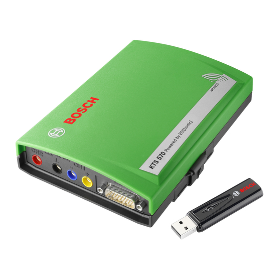
KTS 530 / 540 / 570 (KTS 5 Series)
de Originalbetriebsanleitung
Modul für die Steuergeräte-Diagnose
es Manual original
Módulo para el diagnóstico de la unidad
de control
nl Oorspronkelijke gebruiksaanwijzing
Module voor de regeleenheiddiagnose
da Original brugsanvisning
Modul til styreenhedsdiagnose
cs Původní návod k používání
Systémový tester pro diagnostiku
ídicích jednotek
en Original instructions
Module for controller diagnosis
it Istruzioni originali
Modulo per la diagnosi di centraline di
comando
pt Manual original
Módulo de diagnóstico de unidades de
comando
no Original driftsinstruks
Modul for styreenhet-diagnose
tr Orijinal işletme talimatı
Kontrol üniteleri arza tehis için sistem
test cihaz
fr Notice originale
Module pour le diagnostic des centrales
de commande
sv Bruksanvisning i original
Modul för styrdonsdiagnosen
fi Alkuperäiset ohjeet
Moduuli ohjainlaitediagnoosiin
pl Oryginalna instrukcja eksploatacji
Moduł do diagnostyki sterowników
zh 原始的指南
用于控制单元诊断的模块
Capítulos
Tabla de contenido

Manuales relacionados para Bosch KTS 5 Serie


Resumen de contenidos para Bosch KTS 5 Serie
- Página 1 KTS 530 / 540 / 570 (KTS 5 Series) de Originalbetriebsanleitung en Original instructions fr Notice originale Modul für die Steuergeräte-Diagnose Module for controller diagnosis Module pour le diagnostic des centrales de commande es Manual original it Istruzioni originali sv Bruksanvisning i original Módulo para el diagnóstico de la unidad Modulo per la diagnosi di centraline di Modul för styrdonsdiagnosen...
- Página 37 Conexión mediante USB Configuración de módulo (DDC) Montaje del soporte de fijación Instrucciones en caso de averías 4.6.1 No se encontró el hardware de diagnóstico 4.6.2 Sin comunicación con la unidad de control Robert Bosch GmbH 1 689 979 987 2015-09-22...
-
Página 38: Símbolos Empleados
Las caciones importantes e indicaciones de seguridad indicaciones de advertencia tienen la siguiente estructura: para Bosch Test Equipment". Es obligatorio prestarles atención y leerlas cuidadosamente antes de la pues- PALABRA CLAVE – Tipo y fuente del peligro! ta en funcionamiento, la conexión y el manejo del... -
Página 39: Descripción Del Producto
(solo KTS 570). de y hacia KTS 540 / 570. Requisitos Si el PC está en un carro Bosch (p. ej. FSA 760. BEA 950) es necesario dotar al adaptador Bluetoo- th-USB de un alargador que alcance fuera del vehícu- 3.2.1... -
Página 40: Volumen De Suministro
(categoría de medición 0 según EN 61010-2-030:2010). El acceso- rio adjunto solo se puede utilizar junto con productos Bosch y para tensiones inferiores al valor de tensión impreso en el accesorio. Si se combinan accesorios debe tenerse cuidado de no sobrepasar el valor de tensión impreso... -
Página 41: Indicación De Estado De Los Led A Y B
8 Grupo alterno (IBOX 01) 9 KTS 570 10 Cable de conexión USB 11 Adaptador Bluetooth USB 12 PC (ordenador portátil) Utilizar el cable de conexión UNI (fig. 3, pos. 2) solo para mediciones inferiores a 30 V. Robert Bosch GmbH 1 689 979 987 2015-09-22... -
Página 42: Instrucciones Para El Diagnóstico De Unidades De Mando
(Diagnostic Device Configuration) (véase ayuda online DDC). En el producto KTS 540 / 570 la actualización del firmware se debe realizar siempre con el cable de conexión USB (no a través de Bluetooth). 1 689 979 987 2015-09-22 Robert Bosch GmbH... -
Página 43: Adaptador Bluetooth Usb
Bluetooth en DDC: "Ajustes >> Ajustes am- pliados >> Controlador Bluetooth". El controlador de Bluetooth recomendado ya está preseleccionado, en caso de anomalía se puede seleccionar otro con- trolador de Bluetooth. Robert Bosch GmbH 1 689 979 987 2015-09-22... -
Página 44: Conexión Mediante Usb
KTS en un carro 2. Conectar el módulo KTS mediante el cable de cone- Bosch (solo es posible a partir de la fecha de fabrica- xión USB con el PC/ordenador portátil. ción 03-2006). -
Página 45: Instrucciones En Caso De Averías
" Causas posibles Qué se puede hacer Cable incorrecto Comprobar si se ha utilizado conectado. el cable correcto. En caso de otros problemas, por favor diríjase a la línea directa de servicio. Robert Bosch GmbH 1 689 979 987 2015-09-22... -
Página 46: Puesta Fuera De Servicio
±0,75 % del valor de medición, adicionalmente ±0,25 % del rango de me- dición Precisión CH2 ±2 % del valor de medición, adicionalmente ±0,5 % del rango de me- dición Resolución 100 µV — 100 mV (en función del rango de medición) 1 689 979 987 2015-09-22 Robert Bosch GmbH... -
Página 47: Especificación Osciloscopio
Tensión de ralentí ≤ 5 V Caudal < 10 Ω (con respuesta acústica) 7.3.6 Medición de diodos (CH1) Propiedad Valor/rango Corriente de medición 2 mA Tensión de ralentí ≤ 5 V Tensión máxima de los dio- 2 V Robert Bosch GmbH 1 689 979 987 2015-09-22... - Página 158 3.5.3 LED A 和 LED B 状态指示灯 3.6 操作 3.6.1 接线图 3.6.2 控制单元诊断提示 3.6.3 万用表和示波器的提示 3.6.4 固件升级 3.7 USB 蓝牙适配器 3.8 Microsoft 蓝牙驱动程序 首次调试 4.1 ESI[tronic] 2.0 软件安装 4.2 设置蓝牙 4.3 通过 USB 连接 4.4 模块配置(DDC) 4.5 固定支架安装 4.6 故障提示 4.6.1 未发现诊断硬件 4.6.2 与控制单元无通信 1 689 979 987 2015-09-22 Robert Bosch GmbH...