Intermatic DDT40 Manual De Instalación Y Funcionamiento
Tabla de contenido
Idiomas disponibles
Idiomas disponibles
Enlaces rápidos
Spring Grove, Illinois 60081
www.intermatic.com
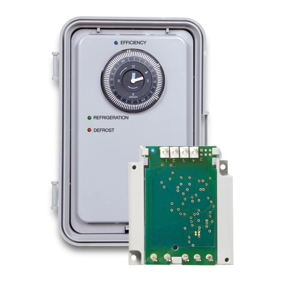
DDT40 Adaptive Defrost Control
Installation and Operation Manual
SAFETY SECTION
Risk of Fire or Electrical Shock
• Disconnect the power at the circuit breaker(s) or disconnect switch(es) before
installing or servicing.
• More than one circuit breaker or disconnect switch may be required to
de-energize the equipment before servicing.
• Installation and/or wiring must be in accordance with the national and local
electrical code requirements.
• For 40 A loads, use #8 AWG wire, for 30 A loads, use #10 AWG rated at least
90º C min. - Use COPPER conductors ONLY.
• Do not exceed maximum current carrying capacity.
• Bonding between conduit connections is not automatic and must be provided as
part of the installation.
• For outdoor locations or wet locations (rain-tight), conduit hubs that comply with
requirements of the UL514B (standard for fitting for conduit and outlet boxes) are
to be used.
• KEEP DOOR CLOSED AT ALL TIMES when not servicing.
• Replace the dead front after servicing or installation, if applicable.
PRODUCT DESCRIPTION
The DDT40 Commercial Refrigeration Control is integrated with ICUBE™ Adaptive Defrost sensing technology. This Adaptive
Defrost Control with ICUBE™ technology transforms a typical Grässlin™ DTAV40 Timer into an Adaptive Defrost Control
which has the ability to skip scheduled defrost events when they are not needed in order to save energy. There is absolutely
no change to the Grässlin™ Defrost Timer load wiring. For more details, see the wiring diagrams on page 7.
The thermistor probes can be installed up to 400 ft (122 m) away from the DDT40. Additionally, it can connect up to four
thermistor probes to a single DDT40 control in order to monitor multiple evaporator coils. To order additional thermistor probe
kits, use part number 178GR10K-1.
Used in electric or hot gas defrost applications where the defrost is terminated when the coil is frost free, as sensed by a
temperature or pressure switch, even though the defrost programmed termination time has not been reached. The time
termination functions as a fail-safe and will terminate the defrost if the temperature or pressure switch fails to do so. The
temperature or pressure switch on the refrigeration coil has contacts which close on a temperature or pressure rise above
freezing, indicating that frost and ice have melted from the coil. Typically a wide differential SPDT temperature switch is used
with it's normally closed contacts wired to the fans thereby delaying the fans from coming on until the coil temperature has
dropped back to below freezing.
WARNING
AVERTISSEMENT
Risque d'incendie ou de choc électrique
• Pour les charges de 40 A, utiliser du fil n° 8 AWG, pour les charges de 30 A,
utiliser n° 10 AWG classés 90° C minimum – Utiliser EXCLUSIVEMENT des
conducteurs en CUIVRE.
• La liaison entre les raccordements de conduits n'est pas automatique et doit être
prévue dans le cadre de l'installation.
• Rotate the timer dial clockwise only, rotating counter-clockwise will damage the
timer.
• Do not move the clock hands on the timer. Moving the clock hands manually may
damage the timer.
• The thermistor wire may be extended up to 400 ft (122 m) using field-supplied
wiring between the DDT40 control and the thermistor probe location.
• Use Intermatic model number DT-B for bracket mounting of the defrost controller
board.
NOTICE
Tabla de contenido

Manuales relacionados para Intermatic DDT40


Resumen de contenidos para Intermatic DDT40
- Página 21 Las sondas del termistor se pueden instalar hasta 122 m (400 pies) del DDT40. De forma adicional, puede conectar hasta cuatro sondas de termistor en un único control DDT40 con el fin de monitorear varios serpentines de evaporador. Para pedir kits de sondas de termistor adicionales, use el número de pieza 178GR10K-1.
-
Página 22: Especificaciones
Note: Consulte las ADVERTENCIAS en la página 21 antes de proceder. Herramientas necesarias • Alicates de punta fina • Pelacables • Destornillador plano pequeño o TORX™ nº 4-40 • Paño de lija o limpiador evaporador • Cortacables Control adaptable de descongelación DDT40... -
Página 23: Montaje De La Caja
FIG. 5 Caja para la instalación. 8. Vuelva a instalar el temporizador en la caja. 9. Una vez que haya terminado de realizar el cableado, debe volver a colocar el frente muerto. Troquel FIG. 6 Troqueles Control adaptable de descongelación DDT40... -
Página 24: Instale La Sonda Del Termistor
2. Conecte el cable de entrada al control DDT40 como se muestra en FIG. 7. El cable de entrada puede insertarse en cualquiera de los cuatro conectores del control DDT40. -
Página 25: Posición Recomendada De La Sonda Del Termistor
1 al 10 para ver detalles adicionales. Nota: Cuando se selecciona el Modo “B” el DDT40 funcionará de la siguiente manera: – Modo de refrigeración: las luces LED roja y verde se apagarán (OFF) (los terminales 1 y 3, 2 y 4 estarán abiertos mientras que los terminales 1 y F estarán cerrados). - Página 26 L2/N Nota: Es necesario aplicar alimentación en los terminales 1 y N para realizar prueba eléctrica. Nota: Aunque el cableado es equivalente, el DDT40 no cabe dentro de una caja Paragon. Esta caja debe cambiarse por la caja Grasslin™ incluida.
- Página 27 DEL CONTROL TÉRMINO 8245 ETIQUETA TERMOSTATO INTERRUPTOR MOTOR DE COMPRESOR DE PRESIÓN VENTILADOR CALEFACTOR DE LÍNEA O VÁLVULA DESCONGELACIÓN SOLENOIDE O SERPETÍN DE CONTACTOR Todas las marcas registradas son de propiedad de sus respectivos dueños. Control adaptable de descongelación DDT40...
-
Página 28: Reemplazo De Temporizadores De Descongelación Existentes
1 y 3 están normalmente abiertos y se cierran durante una descongelación para energizar los calentadores de descongelación; los contactos entre los terminales 2 y 4 están normalmente cerrados con S1 en la posición “A” y abiertos durante una descongelación para desenergizar la refrigeración y los ventiladores. Control adaptable de descongelación DDT40... -
Página 29: Establecimiento De La Duración Máxima De Descongelación
FIG. 11 Colocar el frente muerto 4. Consulte la TABLA 2 y la FIG. 12 o FIG. 13 para verificar LED azul el funcionamiento correcto del control DDT40. LED verde Diagnóstico Modo Estado... -
Página 30: Funcionalidad Del Control Ddt40
• Modo de calibración – el módulo de control DDT40 entra en el modo de calibración después de la primera desconge- lación programada y después de cada ciclo de descongelación permitido. Durante la calibración el control establece un comportamiento inicial del serpentín.