Nice Road200 Instrucciones Y Advertencias Para El Instalador
Tabla de contenido
Idiomas disponibles
Idiomas disponibles
Enlaces rápidos
ENGLISH
OPERATING LIMITS:
in general, ROAD400 is suitable for the automation of gates featuring leaves up to 8 m wide
and weighing up to 400 kg, as shown in Tables 1 and 2.
The length of the leaf makes it possible to determine both the maximum number of cycles per hour and consecutive
cycles, while the weight makes it possible to determine the reduction percentage of the cycles and the maximum speed
allowed.
TABLE 1 - Limits in relation to the length of the leaf
Leave width m
Up to 5
5 - 7
7 - 8
TABLE 2 - Limits in relation to the weight of the leaf
Leaf weight Kg
Up to 200
200÷300
300÷400
TECHNICAL CHARACTERISTICS:
Nice S.p.a., in order to improve its products, reserves the right to modify their
technical characteristics at any time without prior notice. In any case, the manufacturer guarantees their functionality
and fitness for the intended purposes. All the technical characteristics refer to a room temperature of 20°C (± 5°C).
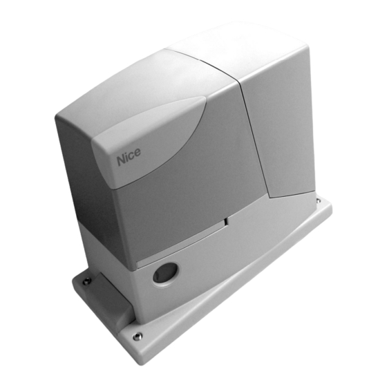
Type
Electromechanical gearmotor for the automatic movement of residential sliding
gates including electronic control unit
Pinion
Z: 15; Module: 4; Pitch: 12.5 mm; Pitch diameter: 60 mm
Peak thrust
12 Nm; corresponds to the ability to start a leaf with a static friction of max. 400 N
moving
Nominal torque
5 Nm; corresponds to the ability to keep a leaf with a dynamic friction of max.
167 N moving
Idling speed
0.25 m/s; the control unit allows 2 speeds to be programmed, equal to: 0.13 m/s
or 0.25 m/s
Nominal torque speed
0,16 m/s
Maximum frequency of
50 cycles per day (the control unit allows up to the maximum described in tables
operating cycles
1 and 2)
Maximum continuous operating time 9 minutes (the control unit limits the continuous operation up to the maximum
described in tables 1 and 2)
ROAD400 Power supply
230 Vac (+10% +15%) 50/60 Hz
ROAD400/V1 Power supply
120 Vac (+10% +15%) 50/60 Hz
Max. absorbed power
210 W (1,1 A)
Insulation class
1 (a safety grounding system is required)
Flashing light output
For 1 LUCYB flashing light (12 V, 21 W lamp)
STOP input
For normally open contacts, for 8.2 KΩ constant resistance, or normally closed
contacts; with self-recognition (any variation from the memorized status causes
the 'STOP' command)
STEP BY STEP input
For normally open contacts (the closing of the contact causes the "STEP-BY-
STEP" command)
Radio AERIAL Input
52 Ω for RG58 or similar type of cable
Radio receiver
Incorporated
Programmable functions
2 ON-OFF functions and 3 adjustable functions (see tables 12 and 14 of
instruction manual ROAD200)
Recognition functions
Open or Normally Closed contact or 8.2 KΩ resistance) Recognition of the length
of the gate and calculation of the slowdown and partial opening points
Operating temperature
-20°C ÷ 50°C
Use in acid, saline or
No
potentially explosive atmosphere
Protection class
IP 44
Dimensions and weight
330 x 195 h 277; 8 Kg
ITALIANO
LIMITI D'IMPIEGO:
generalmente ROAD400 è in grado di automatizzare cancelli con peso fino a 400 Kg oppure lun-
ghezza fino a 8 m secondo quanto riportato nelle tabelle 1 e 2.
La lunghezza dell'anta permette di determinare il numero massimo di cicli per ora e di cicli consecutivi mentre il peso
permette di determinare la percentuale di riduzione dei cicli e la velocità massima consentita.
TABELLA 1- Limiti in relazione alla lunghezza dell'anta
Lunghezza anta metri
Fino a 5
5 - 7
7 - 8
TABELLA 2- Limiti in relazione al peso dell'anta
Peso anta Kg
Fino a 200
200÷300
300÷400
CARATTERISTICHE TECNICHE:
Con lo scopo di migliorare i propri prodotti, Nice S.p.a si riserva il diritto modifi-
che le caratteristiche tecniche in qualsiasi momento e senza preavviso pur mantenendo funzionalità e destinazione
d'uso. Tutte le caratteristiche tecniche riportate si riferiscono alla temperatura ambientale di 20°C (± 5°C).
Tipologia
Motoriduttore elettromeccanico per il movimento automatico di cancelli scorrevoli
per uso residenziale completo di centrale elettronica di controllo
Pignone
Z: 15; Modulo: 4; Passo: 12,5 mm; Diametro primitivo: 60 mm
Coppia massima allo spunto
12 Nm; corrispondente alla capacità di mettere in movimento un'anta con attrito
statico fino a 400 N
Coppia nominale
5 Nm; corrispondente alla capacità mantenere in movimento un'anta con attrito
dinamico fino a 167 N
Velocità a vuoto
0.25 m/s; la centrale consente di programmare 2 velocità, pari a: 0,13 m/s o
0,25 m/s
Velocità alla coppia nominale
0,16 m/s
Frequenza massima cicli di
50 cicli/giorno (la centrale limita i cicli al massimo previsto nelle tabelle 1 e 2)
funzionamento
Tempo massimo funzionamento 9 minuti (la centrale limita il funzionamento continuo al massimo previsto nelle tabelle
continuo
1 e 2)
Alimentazione ROAD400
230 Vac (+10% +15%) 50/60 Hz
Alimentazione ROAD400/V1
120 Vac (+10% +15%) 50/60 Hz
Potenza massima assorbita
210 W (1,1 A)
Classe di isolamento
1 (è necessaria la messa a terra di sicurezza)
Uscita lampeggiante
Per 1 lampeggiante LUCYB (lampada 12 V, 21 W)
Ingresso STOP
Per contatti normalmente chiusi, normalmente aperti oppure a resistenza costante
8,2 KΩ; in autoapprendimento (una variazione rispetto allo stato memorizzato
provoca il comando "STOP")
Ingresso PP
Per contatti normalmente aperti (la chiusura del contatto provoca il comando P.P.)
Ingresso ANTENNA Radio
52 Ω per cavo tipo RG58 o simili
Ricevitore radio
Incorporato
Funzioni programmabili
2 funzioni di tipo ON-OFF e 3 funzioni regolabili (vedere tabelle 12 e 14 del
manuale istruzioni ROAD200)
Funzioni in autoapprendimento
Autoapprendimento del tipo di dispositivo di "STOP" (contatto NA, NC o resistenza
8,2 KΩ) Autoapprendimento della lunghezza del cancello e calcolo dei punti di
rallentamento ed apertura parziale
Temperatura di funzionamento
-20°C ÷ 50°C
Utilizzo in atmosfera
particolarmente acida o salina
No
o potenzialmente esplosiva
Grado di protezione
IP 44
Dimensioni e peso
330 x 195 h 277; 8 Kg
Max cycle/hour
Max. no. of consecutive cycles
20
15
16
12
14
9
% cycles
100%
85%
70%
Cicli/ora massimi
Cicli consecutivi massimi
20
15
16
12
14
9
Percentuale cicli
100%
85%
70%
Road400
for sliding gates
EN -
Addendum to manual ROAD200
IT -
Addendum al manuale ROAD200
FR -
Addendum au manuel ROAD200
ES -
Addendum al manual ROAD200
DICHIARAZIONE CE DI CONFORMITÀ / CE DECLARATION OF CONFORMITY
Nota - Il contenuto di questa dichiarazione corrisponde a quanto dichiarato nell'ultima revisione disponibile, prima della stampa di questo manuale, del documen-
to ufficiale depositato presso la sede di Nice Spa. Il presente testo è stato riadattato per motivi editoriali. / Note - The contents of this declaration correspond to
those of the last revision available of the official document, deposited at the registered offices of Nice S.p.a., before printing of this manual. The text herein has been
re-edited for editorial purposes.
Numero / Number: 297/ROAD400
Il sottoscritto Lauro Buoro in qualità di Amministratore Delegato, dichiara sotto la propria responsabilità che il prodotto: / The undersigned Lauro Buo-
ro, managing director, declares under his sole responsibility that the following product:
Nome produttore / Manufacturer's name: NICE s.p.a.
Indirizzo / Address: Via Pezza Alta 13, 31046 Z.I. Rustignè, Oderzo (TV) Italia / Italy
Tipo / Type: Motoriduttore elettromeccanico "ROAD400" con centrale incorporata / "ROAD400" ac electromechanical gearmotor with built-in control unit
Modello / Models: ROAD400
Risulta conforme a quanto previsto dalla direttiva comunitaria: / Satisfies the essential requirements of the following Directives:
• 98/37/CE (89/392/CEE modificata) DIRETTIVA 98/37/CE DEL PARLAMENTO EUROPEO E DEL CONSIGLIO del 22 giugno 1998 concernente il
ravvicinamento delle legislazioni degli Stati membri relative alle macchine. / DIRECTIVE 98/37/CE COUNCIL of June 22, 1998, for the harmonisation
of the legislations of member States regarding machines.
Come previsto dalla direttiva 98/37/CE si avverte che non è consentita la messa in servizio del prodotto sopra indicato finché la macchina, in cui il pro-
dotto è incorporato, non sia stata identificata e dichiarata conforme alla direttiva 98/37/CE / As specified in the directive 98/37/CEE use of the prod-
uct specified above is not admitted until the machine on which it is mounted has been identified and declared as conforming to the directive
98/37/CEE.
Inoltre risulta conforme ai requisiti essenziali richiesti dall'articolo 3 dalla seguente direttiva comunitaria, per l'uso al quale i prodotti sono destinati: /
Furthermore, the product complies with the essential requisites specified in article 3 of the following EC directive, for the use the products have been
manufactured for:
• 1999/5/CE DIRETTIVA 1999/5/CE DEL PARLAMENTO EUROPEO E DEL CONSIGLIO del 9 marzo 1999 riguardante le apparecchiature radio e le
ap parecchiature terminali di telecomunicazione e il reciproco riconoscimento della loro conformità1995/5/CE. / DIRECTIVE 1999/5/EC OF THE
EUROPEAN PARLIAMENT AND OF THE COUNCIL of March 9, 1999 concerning radio equipment and telecommunications terminal equipment and
mutual recognition of their conformity.
Secondo le seguenti norme armonizzate / According to the following harmonised standards
protezione della salute / health protection: EN 50371:2002;
compatibilità elettromagnetica / electromagnetic compatibility: EN 301 489-1V1.8.1:2008; EN 301 489-3V1.4.1:2002
spettro radio / radio range: EN 300220-2V2.1.2:2007
Inoltre il prodotto risulta conforme a quanto previsto dalle seguenti direttive comunitarie: / Furthermore, the product complies with the specifications
of the following EC directives:
• 2006/95/CEE(ex direttiva 73/23/CE) DIRETTIVA 2006/95/CE DEL PARLAMENTO EUROPEO E DEL CONSIGLIO del 12 dicembre 2006 concer-
nente il ravvicinamento delle legislazioni degli Stati membri relative al materiale elettrico destinato ad essere adoperato entro taluni limiti di tensio-
ne/2006/95CE. / DIRECTIVE 2006/95/EC OF THE COUNCIL of dicember 12, 2006 for the harmonisation of the legislations of member States regar-
ding electrical equipment designed to be used within certain voltage limits
Secondo la seguente norma armonizzata: / According to the following harmonised standards:
EN 60335-1:1994+A11:1995+A1:1996+A12:1996+A13:1998+A14:1998+A15:2000+A2:2000+A16:2001
• 2004/108/CEE(ex direttiva 89/336/CEE) DIRETTIVA 2004/108/CE DEL PARLAMENTO EUROPEO E DEL CONSIGLIO del 15 dicembre 2004 con-
cernente il ravvicinamento delle legislazioni degli Stati membri relative alla compatibilità elettromagnetica e che abroga la direttiva 89/336/
CEE/2004/108/CEE. / DIRECTIVE 2004/108/EEC OF THE COUNCIL of dicember 15, 2004, for the harmonisation of the legislations of member Sta-
tes regarding electromagnetic compatibility
Secondo le seguenti norme armonizzate: / According to the following harmonised standards: EN 61000-6-2:2005; EN 61000-6-3:2001+A11:2004
Inoltre risulta conforme, limitatamente per le parti applicabili, alle seguenti norme: / Furthermore, complies with the specifications, limitedly for the
applicable the following standards: EN 60335-1:2002+A1:2004+A11:2004+A12:2006+ A2:2006, EN 60335-2-103:2003, EN 13241-1:2003;
EN 12453:2002; EN 12445:2002; EN 12978:2003
Oderzo, 29 Settembre 2008 / Oderzo, 29 September 2008
LIMITES D'UTILISATION:
généralement ROAD400 est en mesure d'automatiser des portails pesant jusqu'à 400
kg ou mesurant jusqu'à 8 m suivant les indications des tableaux 1 et 2. La longueur du portail permet de calculer le
nombre maximum de cycles à l'heure et de cycles consécutifs tandis que le poids permet de calculer le pourcentage de
réduction des cycles et la vitesse maximum admissible.
TABLEAU 1- Limites suivant la longueur du portail
Longueur du portail en mètres
Cycles/heure maximums
Jusqu'à 5
5 - 7
7 - 8
TABLEAU 2 - Limites suivant le poids du portail
Poids portail en kg
Jusqu'à 200
200÷300
300÷400
CARACTÉRISTIQUES TECHNIQUES:
modifier les caractéristiques techniques à tout moment et sans préavis, en garantissant dans tous les cas le bon fonc-
tionnement et le type d'utilisation prévus. N.B.: toutes les caractéristiques techniques se réfèrent à la température de
20°C (± 5°C).
Typologie
Opérateur électromécanique pour le mouvement automatique de portails coulissants
pour usage résidentiel avec logique électronique de commande incorporée
Pignon
Z: 15; Module: 4; Pas: 12,5 mm; Diamètre primitif: 60 mm
Couple maximum au démarrage 12 Nm; correspondant à la capacité de mettre en mouvement un portail avec f
riction statique jusqu'à 400 N
Couple nominal
5 Nm; correspond à la capacité de maintenir en mouvement un portail avec
friction dynamique jusqu'à 167 N
Vitesse à vide
0,25 m/s; la logique de commande permet de programmer 2 vitesses, égales à:
0,13 m/s ou à 0,25 m/s
Vitesse a couple nominal
0,16 m/s
Fréquence maximum des cycles 50 cycles/jour (la logique limite les cycles au maximum prévu dans les
de fonctionnement
(tableaux 1 et 2)
Temps maximum de
9 minutes (la logique limite le fonctionnement continu au maximum prévu dans les
fonctionnement continu
tableaux 1 et 2)
Alimentation ROAD400
230 Vac (+10% +15%) 50/60 Hz
Alimentation ROAD400/V1
120 Vac (+10% +15%) 50/60 Hz
Puissance maximum absorbée
210 W (1,1 A)
Classe d'isolement
1 (la mise à la terre est nécessaire)
Sortie clignotant
Pour 1 clignotant LUCYB (Ampoule 12 V, 21 W)
Entrèe STOP
Pour contacts normalement fermés, normalement ouverts ou à résistance
constante 8,2 KΩ; en auto-apprentissage (une variation par rapport à l'état
mémorisé provoque la commande "STOP")
Entrèe PP
Pour contacts normalement ouverts (la fermeture du contact provoque la
commande P.P.)
Entrèe ANTENNE Radio
52 Ω pour câble type RG58 ou similaires
Récepteur radio
Incorporé
Fonctions programmables
2 fonctions de type ON-OFF et 3 fonctions réglables (voir tableaux 12 et 14 du
guide d'instructions ROAD200)
Fonctions en
Auto-apprentissage du type de dispositif de "STOP"(contact NO, NF ou résistance
auto-apprentissage
8,2 KΩ) Auto-apprentissage de la longueur du portail et calcul des points de
ralentissement et ouverture partielle)
Température de fonctionnement -20°C ÷ 50°C
Utilisation en atmosphère
particulièrement acide ou saline Non
ou potentiellement explosive
Indice de protection
IP 44
Dimensions et poids
330 x 195 h 277; 8 Kg
DE -
Nachtrag zur Anleitung ROAD200
PL -
Załącznik do instrukcji ROAD200
NL -
Addendum bij de handleiding
ROAD200
Revisione / Revision: 0
Accessori / Accessories:
sicurezza elettrica / electrical safety: EN 60950-1:2006;
Lauro Buoro
(Amministratore Delegato /
Managing Director)
FRANÇAIS
Cycles consécutifs maximums
20
16
14
Pourcentage cycles
100%
85%
70%
dans le but d'améliorer ses produits, Nice S.p.a. se réserve le droit de
15
12
9
Capítulos
Tabla de contenido

Manuales relacionados para Nice Road200


Resumen de contenidos para Nice Road200
- Página 2 Nice S.p.a., a fin de mejorar sus productos, se reserva el derecho de modificar TECHNISCHE MERKMALE: für eine Verbesserung der Produkte behält sich Nice S.p.A. das Recht vor, die technischen las características técnicas en cualquier momento y sin previo aviso, garantizando la funcionalidad y el uso previsto.
- Página 92 Road200 Índice: pág. Advertencias Otras informaciones Botones de programación Descripción del producto y uso previsto Programaciones Límites de utilización 7.2.1 Funciones de primer nivel (funciones ON-OFF) 101 Instalación típica 7.2.2 Programación de primer nivel Lista de los cables (funciones ON-OFF) 7.2.3...
-
Página 93: Descripción Del Producto Y Uso Previsto
• Antes de acceder a los bornes en el interior de la tapa del ROAD200, • Está prohibido utilizar ROAD200 con una finalidad diferente de aque- desconecte todos los circuitos de alimentación;... -
Página 94: Límites De Utilización
2.1) Límites de utilización Los datos referidos a las prestaciones de ROAD200 están indicados en el capítulo “8 Características técnicas” y son los únicos valores que permiten la evaluación correcta de la idoneidad para su uso. Generalmente, ROAD200 es adecuado para automatizar puertas de hasta 200 kg de peso o de hasta 5 m de largo, según las indicaciones de las tablas 1 y 2. -
Página 95: Instalación
3) Instalación La instalación de ROAD200 debe ser efectuada por personal cualificado, respetando las leyes, normas y reglamentos y las indicaciones de las presentes instrucciones. 3.1) Controles preliminares Antes de comenzar con la instalación de ROAD200 es necesario • Controle que la zona de fijación del motorreductor permita el des- efectuar los siguientes controles: bloqueo y una maniobra manual fácil y segura. -
Página 96: Instalación De Los Diferentes Dispositivos
Si la cremallera está instalada, una vez fijado el motorreductor, ajuste los pasadores de regulación, como muestra la figura 8 para colocar el piñón de ROAD200 a la altura justa dejando 1÷2 mm de juego desde la cremallera. Por el contrario, para fijar la cremallera: 6. - Página 97 1. Para desmontar la tapa de protección y acceder a la central elec- primer anillo sujetacable. trónica de control de ROAD200 quite el tornillo del costado y 5. Conecte los demás cables según el esquema de la figura 15. extraiga la tapa tirando de ella hacia arriba.
-
Página 98: Descripción De Las Conexiones Eléctricas
7 - 8 Luz intermitente en esta salida es posible conectar una luz intermitente NICE “LUCY B” con una bombilla de 12V 21W tipo automóvil. Durante la maniobra parpadea con una frecuencia de 0,5s encendida y 0,5s apagada 4) Controles finales y puesta en marcha Antes de comenzar el control y de poner en marcha la automatiza- ción, se aconseja colocar la puerta en la mitad de su carrera para... -
Página 99: Aprendizaje De La Longitud De La Puerta
30cm y 50 cm del fin 5. Controle que la fijación del motorreductor ROAD200, de la cre- de carrera de apertura deberá desacelerar y detenerse, por la mallera y de los soportes de fin de carrera sean firmes, estables activación del fin de carrera, a 2÷3 cm del tope mecánico de... -
Página 100: Memorización De Los Transmisores
4.7) Memorización de los transmisores Cada transmisor es reconocido por el radiorreceptor a través de un "código" que es diferente de cualquier otro transmisor. Por tal razón, se requiere una etapa de "memorización" con la que se prepara al receptor para que reconozca cada uno de los transmisores. La memoriza- ción de los transmisores puede ejecutarse de 2 modos: Tabla 5: memorización Modo I Modo I: en este modo la función de los botones del transmisor es... -
Página 101: Memorización A Distancia
TX y después cerca del RX y por último por el centro entre los dos tivos. puntos y controle que el dispositivo siempre se accione pasando Para el ensayo del ROAD200 ejecute la siguiente secuencia de ope- del estado activo al estado de alarma y viceversa; por último, raciones: compruebe que provoque en la central la acción prevista, por... -
Página 102: Puesta En Servicio
“puesta en servicio”), número de matrícula, año de fabrica- ción y marcado “CE”. 6) Mantenimiento y desguace En este capítulo se mencionan las informaciones para realizar el plan de mantenimiento y el desguace de ROAD200. 6.1) Mantenimiento Para mantener el nivel de seguridad constante y para garantizar la 2. -
Página 103: Programaciones
(véase la tabla 15). Si la función está desactivada, el funcionamiento es “semiautomático”. Durante el funcionamiento normal de ROAD200 los leds L2 y L3 están encendidos o apagados de acuerdo con el estado de la función que estos representan, por ejemplo L3 está encendido si la función “Cierre automático” está activa.”. -
Página 104: Programación De Segundo Nivel (Parámetros Regulables)
7.2.4) Programación de segundo nivel (parámetros regulables) Los parámetros regulables se configuran en fábrica como se muestra en la tabla 15 con: “ “ pero pueden cambiarse en cualquier momen- to, tal como indicado en la tabla 16. Tenga cuidado al efectuar este procedimiento porque hay un tiempo máximo de 10s entre que se pulsa un botón y el otro, por el contrario, el procedimiento termina automáticamente, memorizando las modificaciones hechas hasta ese momento. -
Página 105: Ejemplo De Programación De Segundo Nivel (Parámetros Regulables)
Espere 10s para salir de la programación por conclusión del tiempo máximo. 7.3) Instalación o desinstalación de dispositivos A una automatización que incorpora el ROAD200 es posible insta- larle o desinstalarle dispositivos en cualquier momento. En particu- lar, a la entrada STOP se le pueden conectar varios tipos de dispo- sitivos, tal como indicado en el párrafo “7.3.1 Entrada STOP”. -
Página 106: Funciones Especiales
7.3.2) Fotocélulas La central de ROAD200 está dotada de la función “Fototest” que Por el contrario, si el test es negativo (fotocélula deslumbrada por el aumenta la fiabilidad de los dispositivos de seguridad, permitiendo sol, cables en cortocircuito, etc.) se detecta la avería y la maniobra no añadir la “categoría 2”... -
Página 107: Solución De Los Problemas
No se acciona ninguna maniobra y el led OK Controle que el ROAD200 esté alimentado con la tensión de red 230V. Controle que los no destella fusibles F1 y F2 no se hayan quemado; si así fuera, controle la causa de la avería y susti- túyalos con otros con las mismas características y del mismo valor de corriente. -
Página 108: Señales En La Central
7.7.2) Señales en la central En la central de ROAD200 hay una serie de LEDs y cada uno de ellos puede dar señales particulares durante el funcionamiento nor- mal o en caso de desperfecto. Tabla 21: leds en los bornes de la central... -
Página 109: Características Técnicas
8) Características técnicas Nice S.p.a., a fin de mejorar sus productos, se reserva el derecho de modificar las características técnicas en cualquier momento y sin pre- vio aviso, garantizando la funcionalidad y el uso previsto. Todas las características técnicas indicadas se refieren a una temperatura ambiente de 20°C (±5°C). - Página 110 Características técnicas transmisor: FLO2 transmisor: FLO2R-S transmisor: SM2 Tipo Transmisor de 2 canales para radiomando Frequenza 433.92MHz Codificación Digital código fijo a 12 Bits, Digital Rolling code a 52 Bits, Digital Rolling code a 64 Bit, tipo FLO tipo FLOR tipo SMILO Botones Alimentación...
-
Página 111: Instrucciones Y Advertencias Para El Usuario Del Motorreductor Road
Establezca con su instala- Nice no es quien escoge los componentes de su auto- dor un plan de mantenimiento con frecuencia perió- matización, este es un trabajo de análisis, evaluación, dica. - Página 112 Está Ud. satisfecho? Si Ud. deseara montar en su casa una nueva automatización, contacte al mismo instalador y a Nice, así podrá contar con la garantía del asesoramiento de un experto y los productos más modernos del mercado, el mejor funcionamiento y la máxima compatibilidad de las automatizaciones.
- Página 158 Aubagne France Fax +34.9.35.88.42.49 Shanghai Tel. +39.06.72.67.17.61 Tel. +33.(0)4.42.62.42.52 info@es.niceforyou.com info@cn.niceforyou.com Fax +39.06.72.67.55.20 Fax +33.(0)4.42.62.42.50 inforoma@niceforyou.com infomarseille@fr.niceforyou.com www.niceforyou.com Nice Gate is the doors and gate automation division of Nice Nice Screen is the rolling shutters and awnings automation division of Nice...