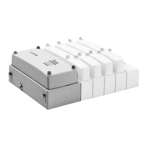
Aventics DeviceNet Manuales
Manuales y guías de usuario para Aventics DeviceNet. Tenemos 1 Aventics DeviceNet manual disponible para descarga gratuita en PDF: Instrucciones De Servicio
Aventics DeviceNet Instrucciones De Servicio (284 páginas)
Tabla de contenido
-
Tabla de Contenido3
-
Zu dieser Dokumentation5
-
Gültigkeit der Dokumentation5
-
Erforderliche und Ergänzende Dokumentationen5
-
Darstellung von Informationen5
-
Sicherheitshinweise6
-
Symbole7
-
Abkürzungen7
-
Sicherheitshinweise7
-
Zu diesem Kapitel7
-
Bestimmungsgemäße Verwendung8
-
Nicht Bestimmungsgemäße Verwendung8
-
Qualifikation des Personals8
-
Allgemeine Sicherheitshinweise9
-
Produkt- und Technologieabhängige Sicherheitshinweise9
-
Einsatzbereiche11
-
Lieferumfang11
-
Gerätebeschreibung12
-
Übersicht über den Buskoppler13
-
Montage14
-
CL03/CL03-XL mit Buskoppler Montieren14
-
Abmessungen15
-
Module Beschriften15
-
Buskoppler Elektrisch Anschließen16
-
Allgemeine Hinweise zum Anschluss des Buskopplers16
-
Buskoppler als Zwischenstation Anschließen18
-
Buskoppler als Letzte Station Anschließen18
-
Spannungsversorgung Anschließen18
-
FE-Anschluss20
-
Inbetriebnahme und Bedienung20
-
Einstellungen Vornehmen20
-
Datenrate Einstellen21
-
Adresse am Buskoppler Einstellen22
-
Diagnosemeldungen Einstellen22
-
Überwachungsschwelle für Ventilversorgung U und U Einstellen23
-
Ventilversorgung Auswählen23
-
Bussystem Konfigurieren26
-
Test und Diagnose27
-
LED-Diagnose27
-
VS mit Buskoppler in Betrieb Nehmen28
-
Austausch29
-
Buskoppler Ersetzen29
-
Multipolmodul durch einen Buskoppler Ersetzen30
-
Pflege und Wartung31
-
Reinigen und Pflegen32
-
Wartung32
-
Abfallentsorgung32
-
10 Wenn Störungen Auftreten32
-
11 Technische Daten33
-
12 Ersatzteile und Zubehör34
-
13 Anhang - Busmasterkonfiguration35
-
Electronic Data Sheet (EDS)35
-
Betriebsverhalten35
-
Anlaufverhalten35
-
Devicenet Objects36
-
Identity Object (Class 0X01)36
-
Message Router Object (Class 0X02)37
-
Devicenet Object (Class 0X03)37
-
Assembly Object (Class 0X04)38
-
Connection Object (Class 0X05)39
-
Discrete Output Point (Class 0X09)41
-
Herstellerspezifische Objekte41
-
I/O Data Object (Class 0X64)41
-
Status Object (Class 0X65)42
-
Module Control Object (Class 0X66)44
-
Module Control Register (MCR)45
-
SPS-Adresszuordnung47
-
14 Stichwortverzeichnis49
-
About this Document53
-
Documentation Validity53
-
Required and Supplementary Documentation53
-
Presentation of Information53
-
Safety Instructions53
-
Symbols54
-
Abbreviations Used55
-
For Your Safety55
-
About this Chapter55
-
Intended Use55
-
Improper Use55
-
Personnel Qualifications56
-
General Safety Instructions56
-
Safety Instructions Related to the Product and Technology57
-
Applications58
-
Delivery Contents58
-
Device Description59
-
Overview of the Bus Coupler60
-
Assembly61
-
Assembling the CL03/CL03-XL with Bus Coupler61
-
Dimensions62
-
Labeling the Module62
-
Connecting the Bus Coupler Electrically63
-
General Notes on Connecting the Bus Coupler63
-
Connecting the Bus Coupler as an Intermediate Station64
-
Connecting the Bus Coupler as a Final Station65
-
Connecting Power Supply65
-
FE Connection67
-
Commissioning and Operation67
-
Making Settings67
-
Setting the Data Rate68
-
Setting the Bus Coupler Address68
-
Setting Diagnostic Messages69
-
Setting Monitoring Threshold for Valve Supply U69
-
And U Q269
-
Selecting the Valve Supply69
-
Configuring the Bus System72
-
Test and Diagnosis73
-
Reading the Diagnostic Leds73
-
Commissioning the VS with a Bus Coupler74
-
Replacement74
-
Replacing a Bus Coupler75
-
Replacing a Multipole Module with a Bus Coupler76
-
Care and Maintenance77
-
Cleaning and Care77
-
Maintenance77
-
Waste Disposal77
-
10 If Malfunctions Occur78
-
11 Technical Data78
-
12 Spare Parts and Accessories79
-
Appendix - Bus Master Configuration80
-
Electronic Data Sheet (EDS)80
-
Operating Behavior80
-
Start-Up Behavior80
-
Devicenet Objects81
-
Identity Object (Class 0X01)81
-
Message Router Object (Class 0X02)82
-
Devicenet Object (Class 0X03)82
-
Assembly Object (Class 0X04)83
-
Connection Object (Class 0X05)84
-
Discrete Output Point (Class 0X09)86
-
Manufacturer Specific Objects86
-
I/O Data Object (Class 0X64)86
-
Status Object (Class 0X65)87
-
Module Control Object (Class 0X66)90
-
Module Control Register (MCR)90
-
PLC Address Assignment93
-
14 Index95
-
Propos de Cette Documentation99
-
A Propos de Cette Documentation99
-
Validité de la Documentation99
-
Documentations Nécessaires et Complémentaires99
-
Présentation des Informations99
-
Consignes de Sécurité99
-
Symboles100
-
Abréviations101
-
Consignes de Sécurité101
-
A Propos de Ce Chapitre101
-
Utilisation Conforme101
-
Utilisation Non Conforme101
-
Qualification du Personnel102
-
Consignes Générales de Sécurité102
-
Consignes de Sécurité Selon le Produit et la Technique103
-
Domaines D'application104
-
Fourniture104
-
Description de L'appareil105
-
Vue D'ensemble du Coupleur de Bus106
-
Montage108
-
Montage du CL03/CL03-XL Avec Coupleur de Bus108
-
Dimensions109
-
Inscription des Modules109
-
Raccordement Électrique du Coupleur de Bus110
-
Remarques Générales Concernant le Raccordement du Coupleur de Bus110
-
Raccordement du Coupleur de Bus en tant que Station Intermédiaire112
-
Raccordement du Coupleur de Bus en tant que Dernière Station112
-
Raccordement de L'alimentation Électrique112
-
Raccord FE114
-
Mise en Service et Utilisation114
-
Procéder aux Paramétrages114
-
Paramétrer le Taux de Données115
-
Paramétrer L'adresse Sur le Coupleur de Bus115
-
Paramétrer les Notifications de Diagnostic116
-
Seuil de Contrôle pour la Tension de Distributeur Réglage pour U Q1 et U Q2117
-
Sélectionner L'alimentation des Distributeurs117
-
Configurer le Système Bus120
-
Test et Diagnostic121
-
Diagnostic Par LED121
-
Mettre en Service le VS Avec Coupleur de Bus122
-
Remplacement123
-
Remplacer le Coupleur de Bus123
-
Remplacer un Module Multipôle Par un Coupleur de Bus124
-
Entretien et Maintenance125
-
Nettoyage et Entretien125
-
Maintenance126
-
Elimination des Déchets126
-
10 En cas de Défaillances126
-
11 Caractéristiques Techniques126
-
12 Pièces de Rechange et Accessoires128
-
13 Annexe - Configuration du Maître129
-
Electronic Data Sheet (EDS)129
-
Comportement en Service129
-
Comportement de Mise en Route129
-
Devicenet Objects130
-
Identity Object (Class 0X01)130
-
Message Router Object (Class 0X02)130
-
Devicenet Object (Class 0X03)131
-
Assembly Object (Class 0X04)132
-
Connection Object (Class 0X05)133
-
Discrete Output Point (Class 0X09)134
-
Objets Propres au Fabricant135
-
I/O Data Object (Class 0X64)135
-
Status Object (Class 0X65)136
-
Module Control Object (Class 0X66)138
-
Module Control Register (MCR)138
-
Affectation des Adresses API140
-
14 Index143
-
Sulla Presente Documentazione147
-
Validità Della Documentazione147
-
Documentazione Necessaria E Complementare147
-
Rappresentazione Delle Informazioni147
-
Indicazioni DI Sicurezza147
-
Simboli148
-
Abbreviazioni149
-
Indicazioni DI Sicurezza149
-
Sul Presente Capitolo149
-
Utilizzo a Norma149
-
Utilizzo Non a Norma150
-
Qualifica del Personale150
-
Avvertenze DI Sicurezza Generali150
-
Indicazioni DI Sicurezza Sul Prodotto E Sulla Tecnologia151
-
Campi DI Impiego152
-
Fornitura152
-
Descrizione Dell'apparecchio153
-
Panoramica Accoppiatore Bus154
-
Montaggio155
-
Montaggio DI CL03/CL03-XL con Accoppiatore Bus155
-
Dimensioni156
-
Dicitura Moduli156
-
Collegamento Elettrico Dell'accoppiatore Bus157
-
Indicazioni Generali Sul Collegamento Dell'accoppiatore Bus157
-
Collegamento Dell'accoppiatore Bus Come Stazione Intermedia159
-
Collegare L'accoppiatore Bus Come Ultima Stazione159
-
Collegamento Dell'alimentazione Elettrica159
-
Attacco FE161
-
Messa in Funzione E Comando161
-
Eseguire Impostazioni161
-
Impostazione Della Velocità DI Trasmissione Dati162
-
Indirizzamento Nell'accoppiatore Bus162
-
Impostazione Delle Segnalazioni Diagnostiche162
-
Soglia DI Sorveglianza Per L'alimentazione Valvole163
-
Regolazione DI U Q1 E U Q2163
-
Selezione Dell'alimentazione Valvole163
-
Configurazione del Sistema Bus166
-
Test E Diagnosi167
-
Diagnosi Tramite LED167
-
Messa in Funzione del Sistema DI Valvole con Accoppiatore Bus168
-
Sostituzione169
-
Sostituzione Dell'accoppiatore Bus169
-
Sostituzione del Modulo Multipolare con un Accoppiatore Bus170
-
Cura E Manutenzione171
-
Pulizia E Cura171
-
Manutenzione172
-
Smaltimento Dei Rifiuti172
-
10 In Caso DI Malfunzionamenti172
-
11 Dati Tecnici172
-
12 Parti DI Ricambio E Accessori173
-
Appendice - Configurazione del Bus Master174
-
Electronic Data Sheet (EDS)174
-
Comportamento Operativo174
-
Comportamento in Avvio174
-
Devicenet Objects175
-
Identity Object (Class 0X01)175
-
Message Router Object (Class 0X02)176
-
Devicenet Object (Class 0X03)176
-
Assembly Object (Class 0X04)177
-
Connection Object (Class 0X05)178
-
Discrete Output Point (Class 0X09)180
-
Oggetti Specifici del Produttore180
-
I/O Data Object (Class 0X64)180
-
Status Object (Class 0X65)181
-
Module Control Object (Class 0X66)183
-
Module Control Register (MCR)184
-
Assegnazione Indirizzi SPS187
-
14 Indice Analitico189
-
Símbolos194
-
Abreviaturas195
-
Montaje202
-
Dimensiones203
-
Conexión FE208
-
Sustitución217
-
Mantenimiento220
-
Índice Temático237
-
Om Denna Dokumentation241
-
Dokumentationens Giltighet241
-
NöDVändig Och Kompletterande Dokumentation241
-
Återgivning Av Information241
-
Säkerhetsföreskrifter241
-
Symboler242
-
Förkortningar243
-
Säkerhetsföreskrifter243
-
Om Detta Kapitel243
-
Tillåten Användning243
-
Ej Avsedd Användning243
-
Förkunskapskrav244
-
Allmänna Säkerhetsanvisningar244
-
Produkt- Och Teknikrelaterade Säkerhetsanvisningar245
-
Användningsområden246
-
Leveransomfattning246
-
Beskrivning Av Enheten247
-
Översikt Av Fältbussnoden248
-
Montering249
-
Montering Av CL03/CL03-XL Med Fältbussnod249
-
Dimensioner250
-
Märkning Av Modulen250
-
Elektrisk Anslutning Av Fältbussnoden251
-
Allmänna Anvisningar För Anslutning Av Fältbussnoden251
-
Ansluta Fältbussnoden Som Mellanstation252
-
Ansluta Fältbussnoden Som Sista Station253
-
Anslutning Av Spänningsförsörjning253
-
FE-Anslutning255
-
Driftstart Och Handhavande255
-
Inställningar255
-
Ställa in Datahastighet256
-
Ställa in Stationsadress256
-
Ställa in Diagnostikmeddelanden257
-
Övervakningströskel För Ventilmatning257
-
Ställa in U Q1 Och U Q2257
-
Välja Ventilernas Spänningsmatning258
-
Konfigurering Av Bussystem260
-
Test Och Diagnostik261
-
Diagnostik Via Lysdioder261
-
Driftstart Av VS Med Fältbussnod262
-
Utbyte263
-
Byta Ut en Fältbussnod263
-
Byta Ut en Multipol-Modul Mot en Fältbussnod264
-
Skötsel Och Underhåll265
-
Rengöring Och Skötsel265
-
Underhåll266
-
Avfallshantering266
-
10 Om Störningar Inträffar266
-
11 Tekniska Data266
-
12 Reservdelar Och Tillbehör267
-
13 Bilaga - Bussmasterkonfiguration268
-
Electronic Data Sheet (EDS)268
-
Driftsbeteende268
-
Startbeteende268
-
Devicenet Objects269
-
Identity Object (Class 0X01)269
-
Message Router Object (Class 0X02)270
-
Devicenet Object (Class 0X03)270
-
Assembly Object (Class 0X04)271
-
0X03 Transportclass_Trigger272
-
0X04 Produced_Connection_Id272
-
0X05 Consumed_Connection_Id272
-
0X07 Produced_Connection_Size272
-
0X08 Consumed_Connection_Size272
-
Connection Object (Class 0X05)272
-
Discrete Output Point (Class 0X09)274
-
Tillverkarspecifika Objekt274
-
I/O Data Object (Class 0X64)274
-
Status Object (Class 0X65)275
-
Module Control Object (Class 0X66)278
-
Module Control Register (MCR)278
-
PLC-Adresstilldelning281
-
14 Nyckelordsregister282