nVent RAYCHEM SC-JBS-L-A Instrucciones De Instalación
Idiomas disponibles
Idiomas disponibles
Enlaces rápidos
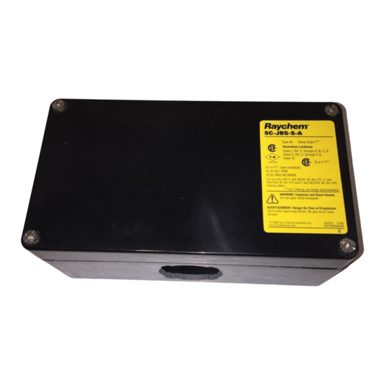
SC-JBS-L-A
Splice Connection with Junction Box Installation Instructions
APPROVALS
Hazardous Locations
Class I, Div. 2, Groups A, B, C, D
Class II, Div. 2, Groups F, G
Class III
– WS
09-IEx-0008X
Ex e IIC T* Gb
(2)
Ex e II T* (see schedule)
IECEx
Ex tD A21 IP66
IECEx BAS 06.0049X
KIT CONTENTS
Item
Qty
Description
A
1
Stand assembly
B
1
Cable lubricant
C
12
Tape strips
D
2
Green/yellow tubes
Coils Kester ® 48 core LF solder for nickel
E
4
F
18
Thomas & Betts splices, spares included
G
1
Junction box
H
1
Lid
I
1
Spanner
J
1
Strain relief
WARNING:
This component is an electrical device that must be installed
correctly to ensure proper operation and to prevent shock or
fire. Read these important warnings and carefully follow all of
the installation instructions.
• To minimize the danger of fire from sustained electrical
arcing if the heating cable is damaged or improperly
installed, and to comply with the requirements of nVent,
agency certifications, and national electrical codes,
ground-fault equipment protection must be used. Arcing
may not be stopped by conventional circuit breakers.
• Be sure all power sources are de-energized before opening box.
• Keep components and heating cable ends dry before and
during installation.
• Component approvals and performance are based on the use
(1)
Ex e II T
– WS
(1)
for T-Rating, see design
documentation
of nVent-specified parts only. Do not use substitute parts or
vinyl electrical tape.
• Soldering tools or torches can cause fire or explosion in
hazardous areas. Be sure there are no flammable materials
or vapors in the area before using these tools.
• Damaged conductors can overheat or short. Do not break
conductor wire strands when scoring the jacketor removing
insulation.
• Use only fire-resistant insulation materials, such as
fiberglass wrap or flame-retardant foam.
• Wrap exposed conductors with supplied tape strips to
prevent shorts.
DESCRIPTION
The nVent RAYCHEM SC-JBS-L-A is a NEMA 4X-rated splice connection
kit designed for use with nVent RAYCHEM 2 and 3SC60, 70, 80 (-CT), 2
and 3SC/H60, 70, 80 (-CT) and 2 and 3SC/F60, 70, 80 (-CR) series heating
cables in hazardous locations.
This kit may be installed at temperatures as low as –40°F (–40°C).
For easier installation, store above freezing until just before installation.
For technical support, call nVent at (800) 545-6258.
TOOLS REQUIRED
• Diagonal cutters
• Utility knife
• Solder tool or torch (with small tip)
• Thomas & Betts TBM5S crimp tool (P/N P000000585) or
WT2000 crimp tool (P/N 273435-000) tool or equivalent.
Crimp tools can be ordered from nVent.
ADDITIONAL MATERIALS REQUIRED
•
Pipe straps (2)
• Glass cloth tape:
– GT-66 for installation temperature above 40°F (4°C)
GS-54 for installation temperature above –40°F (–40°C)
–
OPTIONAL MATERIALS
• Recommended conduit drain:
JB-DRAIN-PLUG-3/4IN (P/N 278621-000)
• Pipe adapter to increase stand height:
SC-JB-PIPE-ADAPTER (P/N P000000648)
A
B
C
D
E
F
Health Hazard: Hot solder can burn eyes and skin. Fumes
during soldering are irritating to eyes and may cause
headache and respiratory system irritation or damage.
Prolonged or repeated exposure to rosin flux fumes during
soldering may result in allergic reaction in a sensitive person,
resulting in asthma symptoms.
Consult MSDS VEN 0043 for further information.
CHEMTREC 24-hour emergency telephone:
(800) 424-9300
Non-emergency health and safety information:
(800) 545-6258
• Slotted screwdriver
• Wire strippers
J
I
H
G
CAUTION:

Manuales relacionados para nVent RAYCHEM SC-JBS-L-A


Resumen de contenidos para nVent RAYCHEM SC-JBS-L-A
- Página 13 Conexión de empalme con caja de conexiones eléctricas Instrucciones de instalación DESCRIPCIÓN El nVent RAYCHEM SC-JBS-L-A es un kit de conexión de empalmes con calificación NEMA 4X diseñado para su uso con cables calefactores nVent RAYCHEM serie 2 y 3SC60, 70, 80 (-CT), 2 y 3SC/H60, 70, 80 (-CT) y 2 y 3SC/F60, 70, 80 (-CR) en lugares peligrosos.
- Página 14 Tipos de cables calefactores Construcción del cable calefactor 2 y 3SC60, 70 y 80 (-CT) 2 y 3SC/H60, 70 y 80 (-CT) 2 y 3SC/F60, 70 y 80 (-CR) Chaqueta exterior Chaqueta exterior Malla de cobre estañado Malla de cobre estañado Chaqueta interior Chaqueta interior Aislamiento del conductor...
- Página 15 • Empuje la malla hacia delante. Utilice un • Retire 20 mm (3/4 pulgadas) de aislamiento y de malla destornillador para abrir la malla. de fibra de vidrio del extremo de cada conductor. Se muestra el cable calefactor 3SC. 20 mm (¾...
- Página 16 Coloque la caja de • • Retire la tuerca conexiones eléctricas de caja. sobre el soporte. Alinee las ranuras del orificio de la caja con la indicación de alineación del soporte. • Vuelva a colocar la tuerca de caja en el soporte. •...
- Página 17 • Crimpe los conductores de cable calefactor y utilice sólo la herramienta crimpadora, el troquel y los empalmes especificados para garantizar una conexión eléctrica adecuada (consulte la tabla). Una conexión crimpada de manera incorrecta puede sufrir recalentamiento. • Después de crimpar un cable suavice los hilos afilados para que no perforen las tiras de cinta en el Paso 17. Empalme Thomas &...
- Página 18 IMPORTANTE: Para asegurar un aislamiento eléctrico adecuado, utilice la cinta de Teflon especificada para alta temperatura que se suministra en el kit. No utilice cinta de vinilo común que carezca de una capacidad nominal de temperatura adecuada. Retire y deseche el protector de las tiras 1era tira 2nda tira 3era y 4ta tiras...