D-Link DES-6500 Manual Del Usuario
Tabla de contenido
Idiomas disponibles
Idiomas disponibles
Enlaces rápidos
Introduction
This Quick Installation Guide gives step-by-step
instructions for setting up the D-Link DES-6500
switch. For more detailed information about the
switch, its components, making network connections,
configuration and technical specifications, please
refer to the User's Guide included in Adobe Acrobat
format on the CD-ROM that was included with the
switch.
Step 1 – Unpacking
Please make sure the following items are present and
undamaged.
Step 2 – Physical Installation
Desktop
For desktop installation, please take time now to
attach the included rubber feet to the base of the
switch.
Rack Mounting
The switch can be mounted in an EIA standard-sized,
19-inch rack, which can be placed in a wiring closet
with other equipment. To install, attach the mounting
brackets on the switch's side panels (two on each side)
and secure them with the screws provided.
After the mounting brackets have been secured, use the
screws provided with the equipment rack to mount the
switch on the rack.
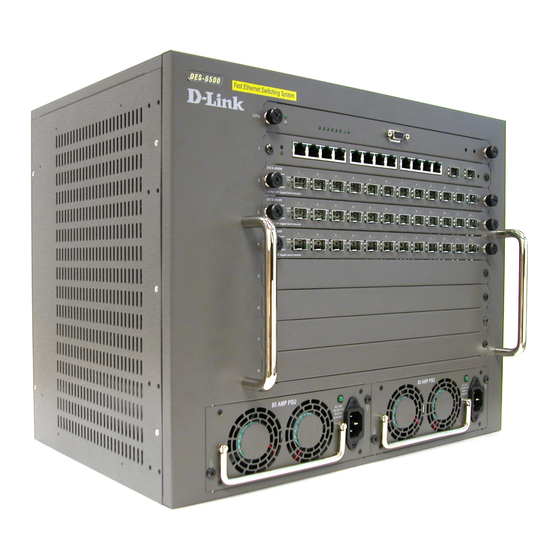
Step 3 – Installing Modules
The DES-6500 ships as a base unit which includes:
♦
DES-6501 Backplane Chassis -- - provides electrical
power to and conveys transmissions between modules
♦
DES-6502 CPU Module -- - Switching and management
module located in the uppermost slot
♦
DES-6511 Redundant Power Supply Module -- -
located in one of the two large slots at the bottom of the
switch
Networking modules sold separately include:
♦
DES-6502 CPU module
♦
DES-6504 12-port 100BASE-FX SFF Fast Ethernet
Switch module
♦
DES-6505 8-port 1000BASE-SX SC Gigabit Ethernet
Switch module
♦
DES-6506 24-port RJ45 Patch Panel module
♦
DES-6507 12-port 1000BASE-T + 2-port Combo SFP slot
Gigabit Ethernet Switch module
♦
DES-6508 16-port 10BASE-T/100BASE-TX (RJ45) Fast
Ethernet Switch module
♦
DES-6509 12-port Mini GBIC Gigabit Ethernet Switch
module
♦
DES-6510 24-port 10/100 RJ21Switch module
♦
DES-6511 Redundant Power Supply module
Carefully follow the procedures defined below to install
additional modules in the switch.
Tabla de contenido

Manuales relacionados para D-Link DES-6500


Resumen de contenidos para D-Link DES-6500
-
Página 10: Paso 1 - Contenido Del Paquete
(use los tornillos suministrados). Paso 3 – Instalación de los módulos El DES-6500 es una unidad base que incluye: ♦ DES-6501 Chasis backplane -- - Proporciona alimentación eléctrica a los módulos y conduce las transmisiones entre ellos. -
Página 11: Paso 4 - Conexión Al Cable De Alimentación Ac
añadir o quitar componentes del sistema. No debe instalarse eliminarse ningún elemento este sistema, sólo puede hacerlo un técnico autorizado. Paso 4 – Conexión al cable de alimentación AC Conecte el cable de alimentación AC en una base de pared (preferiblemente una con toma de tierra y con protección de sobretensión) y en un módulo fuente de alimentación redundante del conmutador. -
Página 12: Información Adicional
También puede encontrar más información en http://www.dlink.com, para Estados Unidos, y en http://www.dlink.co.uk, para Gran Bretaña. Las direcciones web D-Link para otros países figuran en la lista de delegaciones D-Link, al final de la Guía del usuario.