Tabla de contenido
Publicidad
Enlaces rápidos
Publicidad
Tabla de contenido

Manuales relacionados para RAM Audio V Serie


Resumen de contenidos para RAM Audio V Serie
- Página 1 Professional Power Amplifiers 6000-9000 9004-9044-12004-12044 Series OPERATION MANUAL BEDIENUNGSANLEITUNG MANUAL DE EMPLEO © 2011 by C.E. Studio-2 s.l. - Spain (EEC) P-6546-564 QXPDQXDoc http://www.ramaudio.com 4/11 e-mail: support@ramaudio.com...
-
Página 2: Safety Precautions
SAFETY PRECAUTIONS SICHERHEITSHINWEISE ADVERTENCIAS WARNING: ACHTUNG!: PRECAUCIÓN: CAUTION VORSICHT ATENCIÓN GEFAHR EINES RISK OF ELECTRIC SHOCK RIESGO DE CHOQUE ELEKTRISCHEN SCHLAGES. DO NOT OPEN ELÉCTRICO. NO ABRIR. NICHT ÖFFNEN! To avoid fire or electrocution risk do not Um Brand oder elektrische Schläge zu expose the unit to rain or moisture. -
Página 3: Tabla De Contenido
Pol.Ind. La Figuera C/Rosa de Luxemburgo nº34 46970 Alaquas - Valencia - SPAIN Phone: +34 96 127 30 54 Fax: +34 96 127 30 56 http://www.ramaudio.com e-mail: support@ramaudio.com P-5435-634 QXPDQXDoc 4/11 RAM Audio ™ , SSP ™ , ICL ™ ® ™... -
Página 4: General Information
· Puerto USB para actualización del · Digital Potentiometers with Encoder firmware y control del DSP. control · RAM Audio Power Management · 25 posiciones de ganancia, modo puente, links de entradas y ICL, con- System figurables desde el panel frontal. -
Página 5: Controls: Where And What
Controls: Lokalisierung der Ubicación y función Where and What? Funktionen de los Controles 2.1 Front Panel 2.1 Frontplatte 2.1 Panel frontal See Figure Siehe Fig. Ver Figura Configuration and signal attenua- Lautstärkeregler: diese ermögli- Configuración y atenuadores de tion level control knobs: Permit chen die Signalstärke am Ausgang. -
Página 6: Rear Panel
Controls: Lokalisierung der Ubicación y función Where and What? Funktionen de los Controles 2.2 Rear Panel 2.2 Rückplatte 2.2 Panel Trasero See Figure Siehe Fig. Ver Fig. ® ® Signal Input: Female Neutrik Eingangssignal: Neutrik -XLR Entrada de señal: conectores hem- ®... -
Página 7: Installation And Operation
Installation and Anschluss und Instalación y Operation Inbetriebnahme operación 3.1 Connections 3.1 Anschlüsse 3.1 Conexionado The Power switch must always be on Bevor Sie diese Einheit an eine Para proceder al conexionado de la uni- the “Off” position before plugging the SHUKO-Steckdose anschließen, schal- dad situe siempre el interruptor de ali- amp to a properly earthed mains sock-... -
Página 8: Dual Channel Mode
Installation and Anschluss und Instalación y Operation Inbetriebnahme operación The amplifier can operate on three dif- Es gibt drei Funktionsmöglichkeiten die- Existen tres modos de funcionamiento ferent configurations: DUAL, LINK or ser Endstufe: Dual, Link und Bridge. Die posibles del amplificador: Dual, Link, o BRIDGE. - Página 9 Dual Channel 2 Ch models Link Inputs 2 Ch models Bridge Mode 2 Ch models...
- Página 10 Dual Channel 4 Channel models Link Inputs 4 Channel models Bridge Mode 4 Channel models Bridge + Dual Mode 3 Channels Mode...
-
Página 11: Configuration
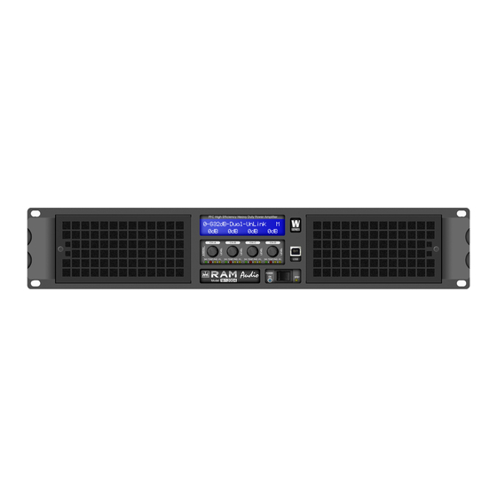
Installation and Instalación y Operation operación 3.2 Configuration 3.2 Configuración Main Screen: shows the current preset name (“G32dB-Dual-UnLink” as default), and the channel attenuation. As an option you can show the out- put VUmeter. The “M” appears at the top right corner if the preset has been changed from the last load. - Página 12 Installation and Instalación y Operation operación Amplifier Setup: when you are in the Main Menu and access to the Amplifier Setup section, you can change different amplifier parameters, change the current preset and protect the access using a password. The Menu development for this section is as follows: Puesta en marcha del amplificador: cuando estás en el menú...
-
Página 13: Problemas Y Soluciones
Installation and Anschluss und Instalación Operation Inbetriebnahme y operación 3.3 Troubleshooting 3.3 Problemlösung 3.3 Problemas y Soluciones In the event of incorrect connection or Sollte sich eine Fehlfunktion ergeben, Si se produce alguna anomalia en la misfunctioning, the amp will activate wird diese durch die LED-Anzeigen auf Instalación o durante el funcionamiento one or more of its LED to warn about... -
Página 14: Protection Systems
- Intelligent Clip Limiter nen. dad de sonido más aceptable incluso The RAM Audio ICL2 is an anticlip system cuando el clip está ocurriendo. Con el sis- to avoid speaker failure and provide more tema ICL2 no puerdes el “punch” de la acceptable sound quality even when clip- música pero el altavoz es mantenido bajo... -
Página 15: Technical Specifications
Technical Technische Especificaciones Specifications Spezifikationen técnicas 4.2 Data 4.2 Technische Daten 4.2 Datos Tecnicos Technical Specifications V-6000 V-9000 V-9004 V-9044 V-12004 V-12044 Output Power 1kHz, 1.0% THD+N @ 2W 2x 3025 W 2x 4400 W 4x 2260 W 4x 3025 W @ 4W 2x 1600 W 2x 2300 W... - Página 16 Manufactured in the EEC by C.E. Studio-2 s.l. Pol. Ind. La Figuera - C/Rosa de Luxemburgo, nº 34 46970 Alaquas - Valencia - SPAIN Phone: +34 96 127 30 54 Fax: +34 96 127 30 56 http://www.ramaudio.com e-mail: support@ramaudio.com...