Registrarse
Cargar
Manuales
Marcas
Balluff Manuales
Sensores de Seguridad
BIR 01-0200-K15ALE-000S92
Balluff BIR 01-0200-K15ALE-000S92 Manuales
Manuales y guías de usuario para Balluff BIR 01-0200-K15ALE-000S92. Tenemos
1
Balluff BIR 01-0200-K15ALE-000S92 manual disponible para descarga gratuita en PDF: Manual De Instrucciones
Balluff BIR 01-0200-K15ALE-000S92 Manual De Instrucciones (194 páginas)
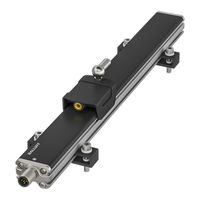
Sistema inductivo rápido de medición de posición
Marca:
Balluff
| Categoría:
Sensores de Seguridad
| Tamaño: 7 MB
Tabla de contenido
Tabla de Contenido
5
Zu dieser Anleitung
7
Mitgeltende Dokumente
7
Verwendete Symbole und Konventionen
7
Bedeutung der Warnhinweise
7
Sicherheitshinweise
8
Bestimmungsgemäße Verwendung
8
Vernünftigerweise Vorhersehbare Fehlanwendung
8
Allgemeine Sicherheitshinweise
8
Lieferumfang, Transport und Lagerung
9
Lieferumfang
9
Transport
9
Lagerbedingungen
9
Produktbeschreibung
10
Produktbeschreibung
11
Bedien- und Anzeigeelemente
11
Typenschild
12
Einbau und Anschluss
13
Einbau Vorbereiten
13
Einbau
13
Geführte Positionsgeber
13
Freie Positionsgeber
14
Elektrischer Anschluss
15
Schirmung und Kabelverlegung
15
Inbetriebnahme und Betrieb
16
Inbetriebnahme
16
Betrieb
17
Hinweise zum Betrieb
17
Wartung
17
Konfiguration mit dem Balluff Engineering Tool (BET)
17
Balluff Engineering Tool (BET)
18
Einheiten Verbinden
18
Konfigurationsmöglichkeiten
18
Reparatur und Entsorgung
19
Reparatur
19
Entsorgung
19
Technische Daten
20
Umgebungsbedingungen
20
Erfassungsbereich/Messbereich
20
Elektrische Merkmale
20
Elektrischer Anschluss
20
Ausgang/Schnittstelle
20
Analoge Strom-/Spannungsschnittstelle
20
IO-Link-Schnittstelle
20
Material
20
Mechanische Merkmale
20
Zulassungen und Kennzeichnungen
21
Zubehör
22
Geführte Positionsgeber
22
Freie Positionsgeber
23
Befestigungsklammer Typ a
23
Befestigungsklammer Typ B
23
Haltewinkel
24
Nutenstein
24
Typenschlüssel
25
About this Guide
31
Other Applicable Documents
31
Symbols and Conventions
31
Explanation of the Warnings
31
Safety Notes
32
Intended Use
32
Reasonably Foreseeable Misuse
32
General Safety Notes
32
Scope of Delivery, Transport and Storage
33
Scope of Delivery
33
Transport
33
Storage Conditions
33
Product Description
34
Construction
34
Function
34
Operating and Display Elements
35
Part Label
36
Installation and Connection
37
Preparing for Installation
37
Installation
37
Guided Targets
37
Floating Targets
38
Electrical Connection
39
Shielding and Cable Routing
39
Startup and Operation
40
Startup
40
Operation
41
Operating Notes
41
Maintenance
41
Configuration with the Balluff Engineering Tool (BET)
42
Balluff Engineering Tool (BET)
42
Connect Units
42
Configuration Options
42
Repair and Disposal
43
Repair
43
Disposal
43
Technical Data
44
Ambient Conditions
44
Detection Range/Measuring Range
44
Electrical Data
44
Electrical Connection
44
Output / Interface
44
IO-Link Interface
44
Materials
44
Mechanical Features
44
Approvals and Markings
45
Accessories
46
Guided Targets
46
Floating Targets
47
Mounting Clamps, Type a
47
Mounting Clamps, Type B
47
Mounting Brackets
48
Slot Nut
48
Type Code
49
A Propos de Cette Notice
55
Autres Documents de Référence
55
Symboles et Conventions Utilisés
55
Signification des Avertissements
55
Consignes de Sécurité
56
Utilisation Conforme aux Prescriptions
56
Mauvais Usage Raisonnablement Prévisible
56
Consignes Générales de Sécurité
56
Fourniture, Transport et Stockage
57
Transport
57
Conditions de Stockage
57
Description du Produit
58
Fonction
58
Eléments de Commande et D'affichage
59
Plaque Signalétique
60
Montage et Raccordement
61
Préparation du Montage
61
Montage
61
Capteurs de Position Guidés
61
Capteurs de Position Libres
62
Raccordement Électrique
63
Blindage et Pose des Câbles
63
Mise en Service et Fonctionnement
64
Mise en Service
64
Fonctionnement
65
Conseils D'utilisation
65
Maintenance
65
Configuration Avec le Logiciel Balluff Engineering Tool (BET)
66
Balluff Engineering Tool (BET)
66
Interconnexion des Unités
66
Possibilités de Configuration
66
Réparation et Élimination
67
Elimination
67
Caractéristiques Techniques
68
Conditions Ambiantes
68
Zone de Détection / Plage de Mesure
68
Caractéristiques Électriques
68
Raccordement Électrique
68
Sortie / Interface
68
Interface Analogique Courant/Tension
68
Interface IO-Link
68
Matériau
68
Caractéristiques Mécaniques
68
Homologations et Certifications
69
Accessoires
70
Capteurs de Position Guidés
70
Capteurs de Position Libres
71
Bride de Fixation Type a
71
Bride de Fixation Type B
71
Equerre de Maintien
72
Coulisseau
72
Code de Type
73
Informazioni Sulle Presenti Istruzioni
79
Documenti DI Riferimento
79
Simboli E Segni Utilizzati
79
Significato Delle Avvertenze
79
Indicazioni Per la Sicurezza
80
Uso Conforme
80
Utilizzo Improprio Ragionevolmente Prevedibile
80
Indicazioni DI Sicurezza Generali
80
Fornitura, Trasporto E Magazzinaggio
81
Trasporto
81
Condizioni DI Magazzinaggio
81
Descrizione del Prodotto
82
Funzionamento
82
Elementi DI Comando E Visualizzazione
83
Targhetta DI Identificazione
84
Montaggio E Collegamento
85
Preparazione del Montaggio
85
Montaggio
85
Trasduttore DI Posizione Guidato
85
Trasduttore DI Posizione Libero
86
Collegamento Elettrico
87
Schermatura E Posa Dei Cavi
87
Messa in Funzione E Funzionamento
88
Messa in Funzione
88
Funzionamento
89
Avvertenze Per Il Funzionamento
89
Manutenzione
89
Configurazione con Il Balluff Engineering Tool (BET)
90
Balluff Engineering Tool (BET)
90
Collegamento Unità
90
Possibilità DI Configurazione
90
Riparazione E Smaltimento
91
Smaltimento
91
Dati Tecnici
92
Condizioni Ambientali
92
Campo DI Rilevamento/Campo DI Misura
92
Caratteristiche Elettriche
92
Collegamento Elettrico
92
Uscita/Interfaccia
92
Interfaccia Analogica Corrente/Tensione
92
Interfaccia IO-Link
92
Materiale
92
Caratteristiche Meccaniche
92
Autorizzazioni E Contrassegni
93
Accessori
94
Trasduttore DI Posizione Guidato
94
Trasduttore DI Posizione Libero
95
Staffa DI Fissaggio Tipo a
95
Staffa DI Fissaggio Tipo B
95
Angolare
96
Tassello Scorrevole
96
Legenda Codici DI Identificazione
97
Acerca de Este Manual
103
Documentos Aplicables
103
Símbolos y Convenciones Utilizados
103
Significado de las Advertencias
103
Palabra de Señalización
103
Uso Debido
104
Aplicación Errónea Previsible desde un Punto de Vista Razonable
104
Indicaciones de Seguridad Generales
104
Volumen de Suministro, Transporte y Almacenamiento
105
Volumen de Suministro
105
Transporte
105
Condiciones de Almacenamiento
105
Descripción de Producto
106
Funcionamiento
106
Elementos de Mando y Elementos Indicadores
107
Placa de Características
108
Montaje y Conexión
109
Preparación del Montaje
109
Montaje
109
Sensores de Posición Guiados
109
Sensores de Posición Libres
110
Conexión Eléctrica
111
Blindaje y Tendido de Cables
111
Puesta en Servicio y Funcionamiento
112
Puesta en Servicio
112
Servicio
113
Indicaciones sobre el Servicio
113
Mantenimiento
113
Configuración con la Balluff Engineering Tool (BET)
114
Balluff Engineering Tool (BET)
114
Conectar las Unidades
114
Posibilidades de Configuración
114
Reparación y Eliminación de Desechos
115
Eliminación de Desechos
115
Datos Técnicos
116
Condiciones Ambientales
116
Zona de Detección/Zona Medible
116
Características Eléctricas
116
Conexión Eléctrica
116
Salida/Interfaz
116
Interfaz Analógica de Corriente/Tensión
116
Interfaz IO-Link
116
Material
116
Características Mecánicas
116
Homologaciones E Identificaciones
117
Accesorios
118
Sensores de Posición Libres
119
Pinza de Fijación Tipo a
119
Pinza de Fijación Tipo B
119
Escuadra de Sujeción
120
Corredera
120
Código de Modelo
121
Sobre Este Manual
127
Documentos Complementares
127
Símbolos E Convenções Empregados
127
Significado Dos Avisos de Alerta
127
Avisos de Segurança
128
Utilização Prevista
128
Aplicação Indevida, Razoavelmente Previsível
128
Avisos Gerais de Segurança
128
Escopo de Fornecimento, Transporte E Armazenamento
129
Abrangência Do Fornecimento
129
Transporte
129
Condições de Armazenamento
129
Descrição Do Produto
130
Função
130
Elementos de Operação E Indicação
131
Etiquetas
132
Montagem E Acoplamento
133
Preparo da Montagem
133
Instalação
133
Encoders de Posição Conduzidos
133
Encoders de Posição Livres
134
Conexão Elétrica
135
Blindagem E Instalação Dos Cabos
135
Colocação Em Funcionamento E Operação
136
Operação
137
Avisos sobre O Funcionamento
137
Manutenção
137
Configuração Com Balluff Engineering Tool (BET)
138
Balluff Engineering Tool (BET)
138
Conectar as Unidades
138
Opções de Configuração
138
Reparo E Eliminação
139
Eliminação
139
Dados Técnicos
140
Condições Ambientais
140
Faixa de Cobertura/Faixa de Medição
140
Características Elétricas
140
Conexão Elétrica
140
Saída/Interface
140
Interface de Corrente/Tensão Analógica
140
Interface IO-Link
140
Material
140
Características Mecânicas
140
Certificações E Marcações
141
Acessórios
142
Encoders de Posição Conduzidos
142
Encoders de Posição Livres
143
Grampo de Fixação Tipo a
143
Grampo de Fixação Tipo B
143
Cantoneira de Suporte
144
Bloco Ranhurado
144
Chave de Tipos
145
关于本操作手册
151
其他适用文档
151
所使用的符号和惯例
151
警告提示的意义
151
安全提示
152
预计可能发生的错误用途
152
一般安全提示
152
供货范围、运输和存放
153
仓储条件
153
产品描述
154
操作和显示元件
155
安装和连接
157
引导性位置指示器
157
自由式位置指示器
158
电气连接
159
屏蔽与布线
159
调试和运行
160
运行提示
161
使用巴鲁夫工程工具 (Bet) 进行配置
162
巴鲁夫工程工具 (Bet)
162
连接单元
162
配置方法
162
维修和废弃处理
163
废弃处理
163
技术数据
164
电气特性
164
电气连接
164
输出端/接口
164
模拟电流/电压接口
164
IO-Link接口
164
机械特性
164
认证和标志
165
引导性位置指示器
166
自由式位置指示器
167
固定夹类型A
167
固定夹类型B
167
支承角钢
168
型号编码
169
この説明書について
175
該当するドキュメント
175
本書で使用するマークと決まりごと
175
警告表示の説明
175
安全に関する注意事項
176
一般に予測される誤用
176
安全に関する一般注意事項
176
同梱品、搬送、保管
177
保管条件
177
製品の説明
178
操作・表示エレメント
179
取付けと接続
181
ガイド付きポインタ
181
浮動ポインタ
182
電気接続
183
シールドとケーブルの配線
183
セットアップと操作
184
操作時の注意
185
メンテナンス
185
Balluff エンジニアリングツール(BET)を使用して設定を行う場合 Balluff エンジニアリングツール(BET
186
ユニットの接続
186
設定方法
186
修理と廃棄
187
テクニカルデータ
188
検出範囲/測定範囲
188
電気的特徴
188
電気接続
188
出力/インタフェース
188
アナログ電流・電圧インターフェース
188
IO-Link インタフェース
188
機械的特徴
188
認証と認証マーク
189
アクセサリ
190
ガイド付きポインタ
190
浮動ポインタ
191
固定用クランプ(タイプ a
191
固定用クランプ(タイプ B
191
マウントブラケット
192
スロットナット
192
型式例
193
Publicidad
Publicidad
Productos relacionados
Balluff BMP 01-EL1PP 1A 00-P S75 Serie
Balluff BMP 01-EL1PP21A-0224-00-P00,5-S4
Balluff BMP 01-EL1PP21A-0256-00-P00,5-S4
Balluff BMP 01-EL1PP21A-0096-00-P00,5-S4
Balluff BMP 01-EL1PP21A-0096-00-P00,5-S75
Balluff BMP 01-EL1PP21A-0192-00-P00,5-S4
Balluff BMP 01-EL1PP21A-0224-00-P02
Balluff BMP 01-EL1PP21A-0256-00-P00,5-S75
Balluff BMP 01-EL1PP21A-0192-00-P00,5-S75
Balluff BMP 01-EL1PP21A-0224-00-P00,5-S75
Balluff Categorias
Sensores de Seguridad
Transductores
Instrumentos de Medición
Equipo Industrial
Conversores de Medios
Más Balluff manuales
Login
Entrar
O
Iniciar sesión con Facebook
Iniciar sesión con Google
Cargar el manual
Cargar desde el disco
Cargar desde la URL