Uline H-10242 Manual De Instrucciones
Tabla de contenido
Idiomas disponibles
Idiomas disponibles
Enlaces rápidos
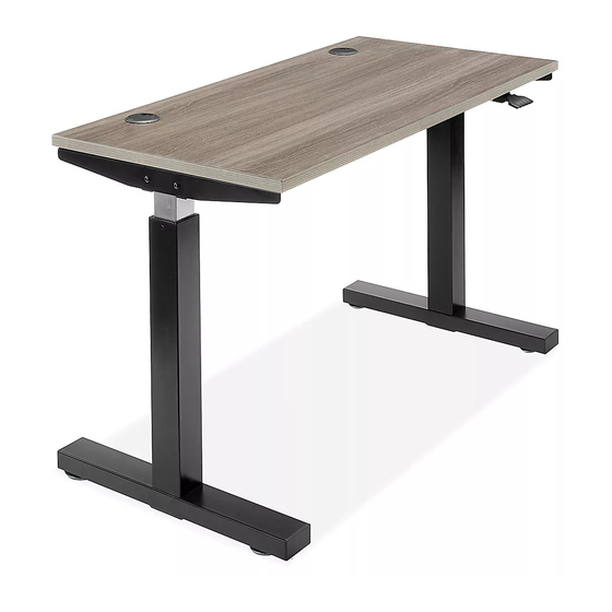
H-10242, H-10243,
H-10244
PNEUMATIC ADJUSTABLE
HEIGHT DESK
TOOLS NEEDED
Phillips Head
Drill
Screwdriver
NOTE: Count and inspect all pieces before
disposing of any carton or packing materials.
#
DESCRIPTION
1
Channel
2
Leg
3
Leg Screw, 6 x 12 mm
4
Side Frame
5
Tabletop
6
Wood Screw, 4.8 x 16 mm
7
Lever
8
Foot
9
Foot Screw, 8 x 65 mm
10
Glide
1.
Remove the two
plastic protectors
on the sides of the
channel (1).
(See Figure 1)
2. For easier assembly, place channel (1) on a raised
surface, such as a table. Insert metal rod located
inside of channel (1) into the mechanism opening
on the top of the leg (2). Repeat this step on the
opposite side. (See Figure 2)
PAGE 1 OF 9
1-800-295-5510
uline.com
Allen Wrench
(included)
QTY
1
2
16
2
1
18
1
2
8
4
Figure 1
1
Plastic Protector
Two Person Assembly
Recommended
ASSEMBLY
Figure 2
2
NOTE: If it is difficult to insert the rod into the
mechanism opening on the top of the leg:
• Align the arrow on the mechanism with
the screw. If metal rod will not insert into
mechanism opening on top of leg, press
center mechanism lever and rotate metal
rod to align arrow with screw on top of metal
rod. (See Figure 2)
• If still experiencing
difficulty inserting
the rod into the
mechanism opening,
slowly press down on
top of leg to turn
mechanism opening.
As opening turns,
push rod into opening
until it is inserted fully.
(See Figure 3)
Para Español, vea páginas 4-6.
Pour le français, consulter les pages 7-9.
Center Mechanism Lever
1
0323 IH-10242
Figure 3
Tabla de contenido

Manuales relacionados para Uline H-10242


Resumen de contenidos para Uline H-10242
-
Página 4: Escritorio De Altura Ajustable Neumático
H-10242, H-10243, H-10244 800-295-5510 uline.mx ESCRITORIO DE ALTURA AJUSTABLE NEUMÁTICO HERRAMIENTAS NECESARIAS Se Recomienda Armar Desarmador Taladro Llave Allen Entre Dos Personas de Cruz (incluida) ENSAMBLE Diagrama 2 NOTA: Cuente e inspeccione todas las piezas Palanca Central para Mecanismo antes de desechar cualquier caja o material de empaque. -
Página 5: Continuación Del Ensamble
CONTINUACIÓN DEL ENSAMBLE 3. Inserte seis tornillos Diagrama 6 Diagrama 4 para patas (3) en los lados y la parte inferior del canal (1). Apriete con la llave Allen. Repita este paso en el lado opuesto. (Vea Diagrama 4) 4. Fije los armazones laterales (4) a cada extremo del canal usando cuatro tornillos para patas (3). -
Página 6: Funcionamiento
Presione lentamente la parte superior de la parte pata. para girar la entrada del mecanismo. Mientras gira la abertura, empuje la varilla dentro de la abertura hasta insertarla por completo. Se recomienda altamente ensamblar entre dos o tres personas. 800-295-5510 uline.mx PAGE 6 OF 9 0323 IH-10242...