LiftMaster 050DCRJWFMC Manual Del Usuario
Tabla de contenido
Idiomas disponibles
Idiomas disponibles
Enlaces rápidos
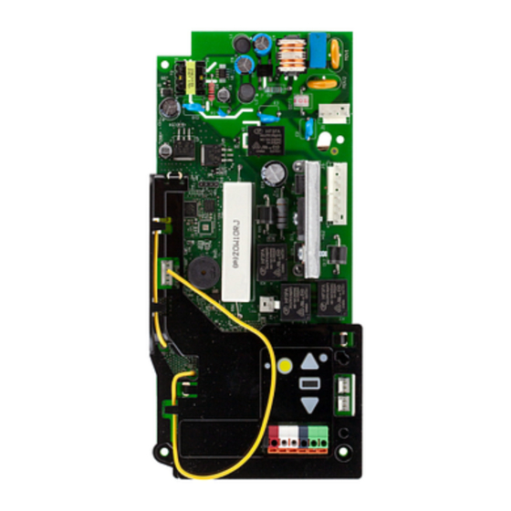
Logic Board
Model 050DCRJWFMC
To prevent possible SERIOUS INJURY or DEATH:
• Disconnect ALL electric and battery power BEFORE performing ANY
service or maintenance.
To prevent damage to the receiver/logic board, DO NOT touch printed
circuit board of replacement receiver/logic board during installation.
ALWAYS wear protective gloves and eye protection when changing the
battery or working around the battery compartment.
WARNING: This product can expose you to chemicals
including lead, which are known to the State of California to
cause cancer or birth defects or other reproductive harm.
For more information go to www.P65Warnings.ca.gov.
NOTICE: This device complies with Part 15 of the FCC rules and Industry Canada's license-
exempt RSSs. Operation is subject to the following two conditions: (1) this device may not
cause harmful interference, and (2) this device must accept any interference received, including
interference that may cause undesired operation.
Any changes or modifications not expressly approved by the party responsible for compliance
could void the user's authority to operate the equipment.
This device must be installed to ensure a minimum 20 cm (8 in.) distance is maintained between
users/bystanders and device.
This device has been tested and found to comply with the limits for a Class B digital device,
pursuant to part 15 of the FCC rules and Industry Canada ICES standard. These limits are
designed to provide reasonable protection against harmful interference in a residential
installation. This equipment generates, uses and can radiate radio frequency energy and, if not
installed and used in accordance with the instructions, may cause harmful interference to radio
communications. However, there is no guarantee that interference will not occur in a particular
installation. If this equipment does cause harmful interference to radio or television reception,
which can be determined by turning the equipment off and on, the user is encouraged to try to
correct the interference by one or more of the following measures:
• Reorient or relocate the receiving antenna.
• Increase the separation between the equipment and receiver.
• Connect the equipment into an outlet on a circuit different from that to which the receiver is
connected.
• Consult the dealer or an experienced radio/TV technician for help.
Before you begin.
Your new MyQ
®
serial number is located on the
replacement label with your replacement logic board. You will need this new MyQ
serial number to connect your opener to the network.
1.
Disconnect power.
3.
Remove the battery cover.
Disconnect the battery. Remove
the battery and set aside (B).
4.
5.
6.
1
2.
Open the front panel (A).
7.
Disconnect all the wiring harnesses
from the logic board (E).
8.
Remove the four screws securing
Add the Step Saver sticker under
the logic board. Rmove the logic
the yellow program button.
board (F), and discard.
Add the Step Saver sticker under
the yellow program button.
Disconnect the wires coming from
the safety reversing sensors,door
control, door lock and cable
tension monitor from the logic
board (C).
Remove the receiver logic board
cover (D).
9.
Install the new logic board and
connect the wiring harnesses.
Route the antenna through the
channel in the cover.
10.
Adhere the new MyQ serial
number label over the original
label on the logic board cover.
11.
Reprogram the travel and test the
safety reversal system (see pages
and 3).
12.
Program all remote controls and
keyless entries (see page 4)..
13.
Use the MyQ app to add the
new MyQ serial number to your
account.
Tabla de contenido

Manuales relacionados para LiftMaster 050DCRJWFMC


Resumen de contenidos para LiftMaster 050DCRJWFMC
- Página 9 Tarjeta Lógica Modelo 050DCRJWFMC Antes de empezar. Su nuevo número de serie de MyQ ® está ubicado en la etiqueta de reemplazo con su tablero lógico de reemplazo. Necesitará este número de serie de MyQ para conectar su abre-puertas a la red.
-
Página 10: Programación Del Recorrido
Ajustes Programación del recorrido UP Button Botón Presione y mantenga presionado el botón de Ajuste hasta que el botón ARRIBA ARRIBA (UP) empiece a parpadear y/o se escuche una señal sonora. Los sensores de seguridad de reversa se desconectarán durante el Botón de Adjustment regulación... - Página 11 Ajustes Prueba del sistema de reversa de seguridad Con la puerta completamente abierta, coloque una tabla de 3.8 cm (1 1/2 de pulg.) de altura (o de 5 x 10 cm [2 x 4 pulg.] acostada en el piso), centrada abajo de la puerta del garaje. Opere la puerta en la dirección hacia abajo.
-
Página 12: Programación
La programación puede realizarse a través del control de la puerta o el botón de aprendizaje del abre-puertas de garaje. Para programar accesorios adicionales consulte las instrucciones provistas con el accesorio o visite LiftMaster.com. Si su vehículo está equipado con un Homelink , puede ®...