Ecco C2013B Instrucciones De Instalación Y Funcionamiento
Tabla de contenido
Idiomas disponibles
Idiomas disponibles
Enlaces rápidos
IMPORTANT! Read all instructions before installing and using. Installer: This manual must be delivered to the end user.
WARNING!
Failure to install or use this product according to manufacturer's recommendations may result in property damage, serious injury, and/
or death to those you are seeking to protect!
Do not install and/or operate this safety product unless you have read and understood the safety information
contained in this manual.
1.
Proper installation combined with operator training in the use, care, and maintenance of emergency warning devices are essential to
ensure the safety of emergency personnel and the public.
2.
Emergency warning devices often require high electrical voltages and/or currents. Exercise caution when working with live electrical
connections.
3.
This product must be properly grounded. Inadequate grounding and/or shorting of electrical connections can cause high current arcing,
which can cause personal injury and/or severe vehicle damage, including fire.
4.
Proper placement and installation is vital to the performance of this warning device. Install this product so that output performance of
the system is maximized and the controls are placed within convenient reach of the operator so that they can operate the system without
losing eye contact with the roadway.
5.
Do not install this product or route any wires in the deployment area of an air bag. Equipment mounted or located in an air bag
deployment area may reduce the effectiveness of the air bag or become a projectile that could cause serious personal injury or death.
Refer to the vehicle owner's manual for the air bag deployment area. It is the responsibility of the user/operator to determine a suitable
mounting location ensuring the safety of all passengers inside the vehicle particularly avoiding areas of potential head impact.
6.
It is the responsibility of the vehicle operator to ensure daily that all features of this product work correctly. In use, the vehicle operator
should ensure the projection of the warning signal is not blocked by vehicle components (i.e., open trunks or compartment doors),
people, vehicles or other obstructions.
7.
The use of this or any other warning device does not ensure all drivers can or will observe or react to an emergency warning signal.
Never take the right-of-way for granted. It is the vehicle operator's responsibility to be sure they can proceed safely before entering an
intersection, drive against traffic, respond at a high rate of speed, or walk on or around traffic lanes.
8.
This equipment is intended for use by authorized personnel only. The user is responsible for understanding and obeying all laws
regarding emergency warning devices. Therefore, the user should check all applicable city, state, and federal laws and regulations. The
manufacturer assumes no liability for any loss resulting from the use of this warning device.
CAUTION!
When drilling into any vehicle surface, make sure that the area is free from any electrical wires, fuel lines, vehicle upholstery, etc. that
could be damaged.
Notes:
1.
Larger wires and tight connections will provide longer service life for components. For high current wires it is highly recommended
that terminal blocks or soldered connections be used with shrink tubing to protect the connections. Do not use insulation displacement
connectors (e.g., 3M Scotchlock type connectors).
2.
Route wiring using grommets and sealant when passing through compartment walls. Minimize the number of splices to reduce voltage
drop. All wiring should conform to the minimum wire size and other recommendations of the manufacturer and be protected from moving
parts and hot surfaces. Looms, grommets, cable ties, and similar installation hardware should be used to anchor and protect all wiring.
3.
Fuses or circuit breakers should be located as close to the power takeoff points as possible and properly sized to protect the wiring and
devices.
4.
Particular attention should be paid to the location and method of making electrical connections and splices to protect these points from
corrosion and loss of conductivity.
5.
Ground termination should only be made to substantial chassis components, preferably directly to the vehicle battery.
6.
Circuit breakers are very sensitive to high temperatures and will "false trip" when mounted in hot environments or operated close to their
capacity.
Installation and Operation Instructions
7 Inch Color Camera System
Page 1 of 5
Tabla de contenido

Manuales relacionados para Ecco C2013B


Resumen de contenidos para Ecco C2013B
- Página 6 Instrucciones de instalación Sistema de cámara color de 7 pulg. ¡IMPORTANTE! Lea todas las instrucciones antes de instalar y utilizar. Instalador: Este manual se debe entregar al usuario final. ¡ADVERTENCIA! Si no sigue las instrucciones del fabricante a la hora de instalar o usar el producto, pueden producirse daños materiales, y lesiones graves o incluso mortales a aquellos que pretende proteger! No instale ni opere este producto de seguridad, a menos que haya leído y comprendido la información de seguridad contenida en este manual.
-
Página 7: Instalación, Cableado Y Función
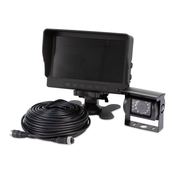
Instalación, cableado y función: Instalación: Cámara modelo C2013B ¡Importante! Monte la cámara en la ubicación que proporcione la mejor vista del área inmediatamente detrás del vehículo. Por lo general, las ubicaciones de montaje hacia la parte superior del vehículo brindan el mejor campo de visión. Las ubicaciones de montaje inferiores reducen el campo de visión y aumentan la probabilidad de daños por rociado del camino. -
Página 8: Identificación De Las Partes Del Monitor
Monitores: Modelos M7000B ¡ADVERTENCIA! Para evitar una descarga eléctrica accidental, NO ABRA LA CAJA DEL MONITOR. Al abrir la caja del monitor, el interior quedará expuesto a condiciones que podrían afectar el desempeño en forma adversa. Cualquier evidencia de alteración de los componentes sellados anulará la garantía. ¡Importante! No exponga el monitor al agua;... - Página 9 Ajustar la visualización OPCIONAL Restablecer Restablecer los ajustes de Girar Para girar la vista fábrica Acercamiento (16:9 or 4:3) Specifications: CÁMARA C2013B MONITOR M7000B Imagen Tamaño de pantalla CMOS 7” (4:3) and (16:9) Requerimiento de voltaje 12-24VCC Controlador 2 cámaras...
- Página 10 Unit 1, Green Park, Coal Road Boise, Idaho 83705 Seacroft, Leeds, England LS14 1FB 800-635-5900 +44 (0)113 2375340 orders@eccogroup.com esguk-code3@eccogroup.com ECCOESG.com ECCOESG.co.uk An ECCO SAFETY GROUP™ Brand ECCOSAFETYGROUP.com © 2021 ECCO, Inc. Todos los derechos reservados. 920-0929-00 Rev. D Página 5 de 5...