Publicidad
Idiomas disponibles
Idiomas disponibles
Enlaces rápidos
Thank you for choosing EAntenna.
All our products are manufactured and developed with the best materials on the market, to offer the best qualities and guarantees to our
customers.
The LFA antennas have an input impedance of 50 Ohm in the antenna, so no coupling is necessary. The loop is at the same time a coupling
system and director element and this presents many advantages when modeling.
The 'real' impedance of each LFA varies greatly. But, the impedance presented at the antenna entry point is always 50 Ohm. Therefore, there
is no limitation on the results of any optimization tool achieved with a single input impedance, but it manages to change the width and length of
the loop keeping the impedance at 50 Ohm. This feature is very important to ensure good performance, bandwidth and low SWR in the
antenna.
This additional flexibility also allows more lateral lobes to be suppressed and a better front-to-back (F / B) ratio compared to traditional Yagis.
With time it is possible to achieve an excellent balance between design, F/B, gain and bandwidth.
Additionally, the proximity of the loop and the antenna entry point make the LFA less susceptible to noise and static nearby. In addition, the low
level of the LFA lateral lobes provides a winning formula for an antenna with super low noise!
We detail the materials used, for their best use and assembly. All the fittings are made of stainless steel and the aluminum is made of T6061 or
T6063 alloy, known as Duralumin that offers the best conditions to be weatherproof, the force of the wind and the best conductivity. The
plastics used, are Polyamide and offer the best hardness and durability for years and years.
We offer warranty on operation, and warranty on hardware, delivering the hardware kit with some additional pieces for possible losses or
forced breaks. In addition, we offer Allen keys and fixed mounting elements.
In the following pages you can see detailed graphics of the parts.
Peso: 9,8 Kg.
Max. Potencia: 10 kW
yagi antenna
yagi antenna
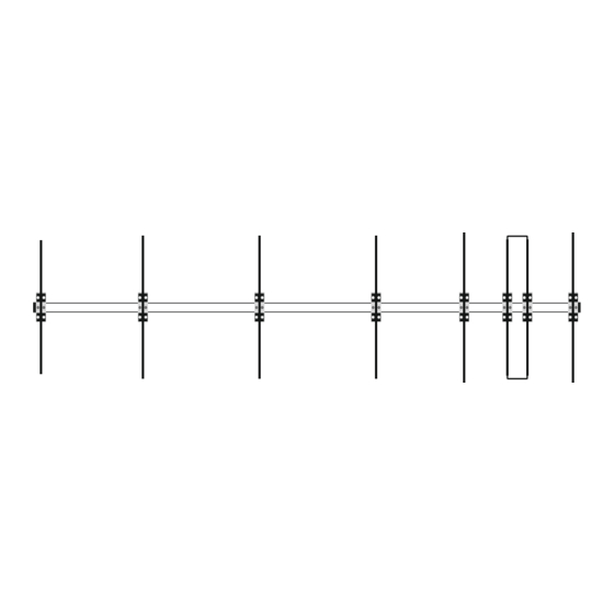
50LFA7
50LFA7
9,38m
17800.06-7
Rev. V1.3 - 23/03//2020
Publicidad

Manuales relacionados para EAntenna 50LFA7


Resumen de contenidos para EAntenna 50LFA7
- Página 7 PLACAS SUJECIÓN MÁSTIL ESPAÑOL La placa de sujeción BOOM/MÁSTIL (EA013020) de 250X100X6mm consta de 12 agujeros; 4 gruesos para los abarcones redondos y 8 para las pletinas (EA010083) que sujetan el BOOM. Los 4 agujeros de mayor grosor tienen la función de que hagan la mayor fuerza sobre el mástil, mediante abarcones redondos de M8. Los abarcones redondos de M8 (A-0163), van fijados mediante arandela DIN 9021 M8 y tuerca DIN 934 M8 proporcionadas en el mismo abarcón, y fijada al mástil con la Mordaza (23035.50).
- Página 8 MAST TO BOOM PLATE ASSEMBLY ENGLISH The clamping plate BOOM / MAST (EA013020) 250X100X6mm consists of 12 holes; 4 thick for round U-bolts and 8 small holes to joint the (EA010083) securing the BOOM. The 4 holes are thicker function that make the greatest force on the mast by means of M8 round U-bolts. Round U-bolts M8 (A-0163), are secured by washer DIN 9021 M8 and nut DIN 934 M8 provided in the same U-bolt, and fixed to the mast with clamp (23035.50).
- Página 9 ESPAÑOL Ajuste del ROE/SWR: Una vez posicionada la antena con sus medidas, quizás necesite algún retoque para conseguir la ROE/SWR deseada. Desplazando la pieza curva hacia adentro o hacia afuera varios milímetros, es la forma de hacerlo. Buscando que el centro de Frecuencia esté...
- Página 10 ENGLISH Adjusting SWR: Once positioned the antenna with your measurements, you may need some fine-tuning to get the SWR desired. Shifting the curve piece inward or outward several millimeters, is the way to go. Looking to the center frequency is 50,150 MHz in the lower SWR.
-
Página 11: Anclaje Para Los Vientos Al Boom
Anclaje para los vientos al Boom ESPAÑOL Para una mayor resistencia al viento, esta antena incluye un sistema de anclajes para su mejor conservación ante la climatología. La placa (EA010007), debe de estar al menos 50cm de separación sobre la placa que sujeta el boom, así... -
Página 14: Plotter De Elevación
Plotter de Elevación... - Página 15 Plotter de Azimut...
- Página 16 Gráfico de R.O.E.