Emerson 80 Serie Instrucciones De Instalación Y Funcionamiento
Ocultar thumbs
Ver también para 80 Serie:
- Instrucciones de instalación y operación (12 páginas) ,
- Instrucciones de instalación y funcionamiento (12 páginas) ,
- Instrucciones de instalación y funcionamiento (12 páginas)
Tabla de contenido
Idiomas disponibles
Idiomas disponibles
Enlaces rápidos
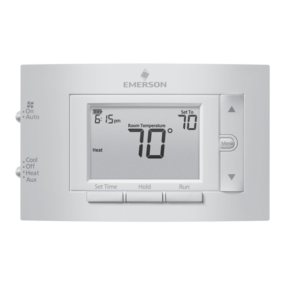
Optional Accessory: Wall Cover-Up Plate F61-2663, 6 3/4" W x 4 1/2" H
INDEX
Thermostat Installation
2-4
Wiring
2
3-4
5-7
5
6
6
7
7-8
8
SPECIFICATIONS
Electrical Rating:
Battery Power ..................................... 20 to 30 VAC, NEC Class II, 50/60 Hz
Input-Hardwire .................................... 20 to 30 VAC, NEC Class II, 50/60 Hz
Terminal Load .......................................... 1.5 A per terminal, 2.5A maximum all terminals combined
Setpoint Range ........................................ 45° to 99° F (7° to 37° C)
Rated Differentials (@ 6°F/ Hr):
Fast
Heat Pump (Heat)................................ 0.9°F
Heat Pump (Cool) ................................ 0.9°F
Auxiliary Heat ...................................... 0.5°F
Operating Ambient .................................. 32°F to +105°F (0° to +41°C)
Display Temperature Range ....................... 32°F to +99°F (0 to 37°C)
Operating Humidity ................................. 90% non-condensing maximum
Shipping Temperature Range ................... -20°F to + 150°F (-29° to +65°C)
Thermostat Dimensions ........................... 3-3/4" H x 6" W x 1-1/8" D
www.white-rodgers.com
www.emersonclimate.com
1F83H-21PR (Programmable)
Installation and Operating Instructions
80 Series Heat Pump Thermostat
Battery Powered or Hardwired with Common
Maximum
Thermostat Applications
Stages
Heat/ Cool
Single Stage Compressor, Heat Pump
Systems (air source or geothermal) -
1 Stage Aux/Emergency Heat
MERCURY NOTICE: This product does not contain
mercury. However, this product may replace a product
that contains mercury. Mercury and products containing
mercury must not be discarded in household trash.
Refer to www.thermostat-recycle.org for information
on disposing of products containing mercury.
Med
Slow
1.2°F
1.7°F
1.2°F
1.7°F
0.75°F
1.9°F
PART NO. 37-7511A-EN
WIRING
Refer to equipment manufacturer's instructions for specific system wiring information. After
wiring, see INSTALLER MENU for proper thermostat configuration. Wiring table shown are
for typical systems and describe the thermostat terminal functions.
Terminal Designations
*Cut W2/E jumper when separate heat sources are used for W2 and E.
IMPORTANT: For Dual Fuel Heat Pump applications, be sure to turn on the Duel Fuel Logic option
(found in the Installer's Menu)
2/1
Precautions
• Do not exceed the specification ratings.
• All wiring must conform to local and national electrical codes and ordinances.
• This control is a precision instrument, and should be handled carefully. Rough handing or
distorting components could cause the control to malfunction.
!
Do not use on circuits exceeding specified voltage.
Higher voltage will damage control and could
cause shock or fire hazard.
Do not short out terminals on gas valve or primary
control to test. Short or incorrect wiring will burn
out thermostat and could cause personal injury
and/or property damage.
1504
THERMOSTAT INSTALLATION
R
Power (24V)
Changeover Terminal-Energized in Cool (O) or Heat (B)
O/B
for Heat Pump or Damper Systems
Y
Heat and Cool Mode 1st Stage Compressor
G
Fan Relay
E*
Auxiliary only Heat Mode (Emergency Heat)
C
Common wire for 24V (optional with batteries)
Heat Pump malfunction / Diagnostic terminal
L
(input signal requires common)
W2*
Heat Mode - 2nd stage
WARNING
To prevent electrical shock and/or equipment
damage, disconnect electrical power to system,
at main fuse or circuit breaker box,until
Terminal Function
Leveling Thermostat
Leveling is for appearance only and
will not affect thermostat operation.
CAUTION
!
installation is complete.
2
Capítulos
Tabla de contenido
Solución de problemas

Manuales relacionados para Emerson 80 Serie


Resumen de contenidos para Emerson 80 Serie
- Página 9 1F83H-21NP (No Programable) INSTALACIÓN DEL TERMOSTATO Instrucciones de instalación y operación Termostato de bomba de calor Serie CONEXIONES CONEX Alimentación por pilas o conexión por cable con neutro Consulte las instrucciones del fabricante del equipo para obtener información específica de las Consulte conexiones.
-
Página 10: Menú De Instalación
MENÚ DE INSTALACIÓN (continuación) MENÚ Ubicación Menú de instalación Menú de Configuración Opciones de las pilas N° N° Descripción predeterminada (Mantenga presionado (Presione (Mantenga Se deben usar pilas alcalinas (iconos intermitentes) Menu durante 8 segundos) Menu dura AA de buena calidad cuando no °F –... -
Página 11: Cómo Usar El Termostato
MENÚ DEL USUARIO MENÚ CÓMO USAR EL TERMOSTATO Para personalizar las opciones del termostato, presione el botón Menu desde la pantalla de inicio. Para perso Use Next (siguiente) para desplazarse por los elementos del menú. Presione para cambiar la Use Next DESCRIPCIÓN GENERAL DEL TERMOSTATO opción. -
Página 12: Solución De Problemas
LÍNEA DE AYUDA PARA EL USUARIO: 1-800-284-2925 termómetro White-Rodgers es una empresa (La Solución de problemas continúa en la página siguiente) de Emerson Electric Co. El logotipo de Emerson es una marca comercial y una marca de www.white-rodgers.com servicio de Emerson Electric Co. www.emersonclimate.com...