Honeywell UDC100 Manual Del Usuario
Idiomas disponibles
Idiomas disponibles
Enlaces rápidos
ENGLISH
UDC100 PID OPTION MANUAL
1 - CONFIGURATION OF THE CONTROL ALGORITHM
Parameter
Action:
Direction of the control, direct or reverse acting.
Typically, reverse control is used for heating and direct control for cooling applications.
Proportional band:
Proportional action is used to achieve stable control and is expressed as the percentage of the input span
over which the output power level is directly proportional to the percentage of error between the PV and
setpoint.
Configurable from 0.0% (ON/OFF control) to 999.9%.
WARNING: The 0.0% value sets the UDC100 to ON/OFF control irrespective of the other parameter settings
e.g. integration and derivative times.
Integration time:
Integral action is used to eliminate any offset between the PV and SP due to proportional action.
Integral time constant configurable from 0 second (OFF) to 5999 seconds.
Setting the integral time to 0 will switch off the integral action.
This parameter is ignored if the proportional band is set to 0.0% (ON/OFF control).
Derivative time:
Derivative action is used to return the PV back to the SP in a quicker time period after a process disturbance.
The function is also utilized to limit the amount of overshoot of the PV during initial start up of a process.
The operation of the derivative action is based on the rate of change of the PV with reference to the SP.
Derivative time constant is configurable from 0 second to 5999 seconds.
Setting the derivative time to 0 will switch off the derivative action.
This parameter is ignored if the proportional band is set to 0.0% (ON/OFF control).
Cycle time:
Configurable up to 256s. WARNING : It is strongly recommended to avoid using cycle times below
5 seconds, otherwise the precision of the output activation timing is not guaranteed.
Max. rate:
Maximum output increase between two consecutive input/output updates configured from 0% to 100%.
Setpoint low limit:
Configurable minimum setpoint value.
Setpoint high limit:
Configurable maximum setpoint value.
Setpoint:
Setpoint value used for control.
Output power high limit:
Power output high limit configurable from 0 to 100% output.
Output power low limit:
Power output low limit configurable from 0 to 100% output.
2 - SETTING THE PID PARAMETERS VIA THE UDC100 MMI
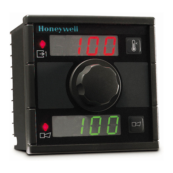
In normal operating conditions, the upper display shows the process variable [PV], (i.e. : 100°C).
When push button 1 is pressed, the setpoint value (flashing) is displayed, (i.e. : 300 °C).
When push button 1 is pressed while the SP is flashing, the display shows «Cod». After 2 seconds, the current value is flashing to indicate that
the user must enter a security code by means of the setpoint knob, to enable access to the PID parameters.
The code is factory set and cannot be changed in the field. The default value is 10.
If the code is entered correctly, the next message is displayed.
If the UDC100 is a two loops model, it is possible to toggle between CH1 and CH2 by pressing push button 1.
When the proportional band menu appears, this parameter can be modified by waiting until the value flashes, the value can then be altered via
the setpoint knob.
Pressing push button 1 while message "Pb" is displayed gives direct access to the next parameter (the integral time constant), and the same
procedure above applies if the value needs to be modified.
Repeat the steps detailed above to modify the derivative time constant.
Used to set the output bias (manual reset) when the integral time constant parameter is set to 0.
Cycle time parameter is used to adjust the time proportional output to achieve optimum control.
Press push button 1 to return to the normal operating mode or wait for message "no" to appear, after a short time the UDC100 will return to
normal PID mode.
It is possible to toggle between "yes" and "no" by pressing push button 1.
Note: If "yes" is selected the UDC100 will enter into manual mode just after leaving configuration mode.
The UDC100 will remain in manual mode until "no" is reselected in configuration mode.
Industrial Measurement and Control
Honeywell-1100 Virginia Drive-Fort Washington, PA 19034
Designation
1
MU1I-6214 02/03
Unit
in 0.1% increment
in 1s increment
in 1s increment
in 0.1s increment
in 0.1% increment
in 1°C increment
In 1°C increment
in 1°C increment
in 0.1% increment
in 0.1% increment
Honeywell
MU1I-6214
02/03

Manuales relacionados para Honeywell UDC100


Resumen de contenidos para Honeywell UDC100
- Página 9 VP (variable para procesar) y el punto de consigna. Configurable desde 0.0% (control ON/OFF) hasta 999.9%. ADVERTENCIA : El valor 0.0% establece el control ON/OFF para el UDC100 independientemente de los demás parámetros establecidos (integración y tiempos derivativos).
- Página 10 Es posible alternar entre « yes » y « no » pulsando el botón 1. Nota : Si se ha seleccionado « yes », el UDC100 se pondrá en modo manual tras salir del modo de configuración. El UDC100 continuará en modo manual hasta que se vuelva a seleccionar « no » en el modo de configuración.
-
Página 11: Establecimiento De Los Parámetros Pid Por Medio Del Control On/Off
El parámetro de bias de salida puede utilizarse para eliminar la desviación entre la VP y el SP cuando el controlador está en modo proporcional y derivativo. NB : El parámetro de bias de salida (rearme manual) es accesible a través de la MMI UDC100 sólo cuando la constante de tiempo integral se ha establecido en 0. - Página 12 Corriente de salida mínima Corriente de salida máxima Límite inferior Límite superior Duración de salida Valor del punto del punto de consigna del punto de consigna de consigna Honeywell Industrial Measurement and Control MU1I-6214 Honeywell-1100 Virginia Drive-Fort Washington, PA 19034 02/03...