Tabla de contenido

Publicidad

Idiomas disponibles
  • ES

Idiomas disponibles

  • ESPAÑOL, página 67

Enlaces rápidos

Notice d'instructions
Instruction manual
Bedienungsanleitung
712B
Gebruiksaanwijzing
Manual de instruccciones
Istruzioni per l'uso
Manual de instruções
Pince multimètre CA/CC
AC/DC clamp meter
Wechsel-/gleichstrommesszange
Stroomtang voor wisselstroom gelijkstroom
Pinza amperimétrica de CA/CC
Multimetro digitale a pinza AC/DC
Pinça amperimétrica CA/CC
1
NU-712B_0618 7 langues.indd 1
22/06/2018 11:50:50

Publicidad

Tabla de contenido
loading

Resumen de contenidos para Facom 712B

  • Página 1 Notice d’instructions Instruction manual Bedienungsanleitung 712B Gebruiksaanwijzing Manual de instruccciones Istruzioni per l’uso Manual de instruções Pince multimètre CA/CC AC/DC clamp meter Wechsel-/gleichstrommesszange Stroomtang voor wisselstroom gelijkstroom Pinza amperimétrica de CA/CC Multimetro digitale a pinza AC/DC Pinça amperimétrica CA/CC NU-712B_0618 7 langues.indd 1...
  • Página 2 ..............3 ..............19 ..............35 ..............51 ..............67 ..............83 ..............99 NU-712B_0618 7 langues.indd 2 22/06/2018 11:50:50...
  • Página 3: Tabla De Contenido

    TABLE DES MATIÈRES 1. Introduction ..............4 2. Informations liées à la sécurité........4 2.1 Mesures de précaution 2.2 Symboles de sécurité 3. Descriptif................7 3.1 Panneau avant 3.2 Écran 4. Utiliser le multimètre............10 4.1 Prise de mesure avec la fonction Smart 4.2 Extinction automatique 4.3 Tension continue (CC) 4.4 Tension alternative (CA) 4.5 Courant alternatif (CA)
  • Página 4: Introduction

    1. Introduction AVERTISSEMENT Assurez-vous de lire et de respecter toutes les procédures de sécurité afin d’éviter tout choc électrique et/ou blessure. Ce multimètre est une pince multimètre digitale, sûre et fiable, bien que de petite taille. Il peut mesurer le courant CA/CC, la tension CA/CC, la résistance et la continuité...
  • Página 5: Mesures De Précaution

    Les mesures de précaution servent à empêcher l’utilisateur d’endommager l’instrument ou l’objet testé. 2.1 Mesures de précaution Respectez les points suivants, afin d’empêcher tout choc électrique possible, toute blessure ou l’endommagement du multimètre : 1. Contrôlez l’absence de dommage sur les câbles de test (isolant et fils) avant l’utilisation.
  • Página 6: Symboles De Sécurité

    16. Le fonctionnement normal du tester peu être perturbé par des perturbations électromagnétique importantes. En cas de mauvais fonctionnement suite à des perturbations électromagnétique il suffira d’éteindre le testeur et le rallumer. En cas de perturbation du testeur par des onde électromagnétique il faut déplacer le testeur à...
  • Página 7: Descriptif

    3. Descriptif 3.1 Panneau avant kHz% %NCV AUTO NU-712B_0618 7 langues.indd 7 22/06/2018 11:50:55...
  • Página 8 1. Pince Pour mesurer le courant alternatif/continu. 2. Garde de protection Permet d’empêcher le contact des mains avec les conducteurs pendant la mesure du courant. 3. Commutateur rotatif Sert à sélectionner la fonction et la plage. 4. MAX/MIN Appuyez sur la touche pour afficher la valeur lue maximum parmi les données mesurées et le symbole «MAX»...
  • Página 9: Écran

    3.2 Écran SYMBOLE DESCRIPTIF AUTO Plage auto Courant/tension alternatif(ve) Courant/tension continu(e) Piles vides Pourcentage (cycle de service) Hertz (fréquence) Volts (tension) Ampères (courant) Ohms (résistance) Ω, kΩ, MΩ Continuité Maintien de l’affichage Indicateur de polarité (négative) NU-712B_0618 7 langues.indd 9 22/06/2018 11:50:55...
  • Página 10: Utiliser Le Multimètre

    4. Utiliser le multimètre 4.1 Prise de mesure avec la fonction Smart Tournez le commutateur rotatif jusqu’à la position «SMART». Les modes par défaut sont «AC Current/Courant alternatif», «DC Current/Courant continu», «AC Voltage/Tension alternative», «DC Voltage/Tension continue», «Resistance/Résistance» ou «Continuity/ Continuité».
  • Página 11: Tension Alternative (Ca)

    4.4 Tension alternative (CA) Insérez le câble de test rouge dans la borne d’«ENTRÉE» et le câble noir dans la borne «COM». Tournez le commutateur rotatif jusqu’à la position « ». Raccordez les câbles de test sur le circuit ou la charge à mesurer.
  • Página 12: Résistance

    4.7 Résistance Coupez toutes les sources d’alimentation et déchargez les condensateurs du circuit à tester. Insérez le câble de test rouge dans la borne d’«ENTRÉE» et le câble noir dans la borne «COM». Tournez l’interrupteur rotatif jusqu’à la position « Ω».
  • Página 13: Rapport Cyclique / Fréquence

    AVERTISSEMENT Afin d’éviter toute blessure ou l’endommagement du multi- mètre, assurez-vous de couper toutes les alimentations et de décharger tous les condensateurs avant de mesurer une continuité. 4.9 Rapport cyclique / Fréquence Insérez le câble de test rouge dans la borne d’«ENTRÉE» et le câble noir dans la borne «COM».
  • Página 14: Caractéristiques Techniques

    5.2 Caractéristiques techniques Précision: ± (% de la mesure + chiffres), garantie 1 an. Température ambiante: 18°C~28°C, humidité : <75%. Coefficient de température: Précision 0,1/°C (0°C~18°C ou 28°C~40°C). 5.2.1 Tension continue (CC) Plage Résolution Précision 0.01V ± (0,5% du résultat + 3 chiffres) 0.1V 600V - Impédance en entrée: 10MΩ.
  • Página 15 5.2.3 Courant alternatif (CA) Résolution Plage Précision 0.01A ± (2,5% du résultat + 8 chiffres) 200A 0.1A 600A ± (3,0% du résultat + 10 chiffres) - Plage de fréquences: 45Hz~65Hz. - Courant d’entrée maxi: jusqu’à 600 A pendant au plus 60 secondes.
  • Página 16: Cycle De Service

    - Tension du circuit ouvert: env. 0,4 V. - Protection contre les surcharges: Valeur efficace 250 V CC ou CA. 5.2.6 Continuité Plage Fonction Si la résistance mesurée est inférieure à 40Ω, le buzzer du multimètre retentit. - Tension du circuit ouvert: env. 0,4 V. - Protection contre les surcharges: Valeur efficace 250 V CC ou CA.
  • Página 17: Remplacer Les Piles

    Ne tentez pas d’effectuer vous-même les réparations ou le calibrage du multimètre à moins que vous ne soyez un professionnel de maintenance expérimenté. AVERTISSEMENT Retirez les câbles de test du multimètre avant d’ouvrir le cache-piles afin d’éviter les dommages et les blessures. Utilisez un chiffon humide et une petite quantité...
  • Página 18: Remplacer Les Câbles De Test

    L’appareil ne doit pas être jeté avec les déchets ménagers; il doit être déposé à un point de collecte dédié. Stanley Black & Decker France 62 CHEMIN DE LA BRUYÉRE 69570 DARDILLY, FRANCE www.facom.com NU-712B_0618 7 langues.indd 18 22/06/2018 11:50:58...
  • Página 19 TABLE OF CONTENTS 1. Introduction ..............20 2. Safety information............20 2.1 Precautions 2.2 Safety symbols 3. Description..............23 3.1 Front panel 3.2 Display 4. Using the meter.............26 4.1 Smart Function Measurement 4.2 Auto Power Off 4.3 DC Voltage 4.4 AC Voltage 4.5 AC Current 4.6 DC Current 4.7 Resistance 4.8 Continuity...
  • Página 20: Introduction

    1. Introduction WARNING Make sure to read and follow all safety procedures to avoid electric shock and/or injury. The meter is a safe, reliable, yet small handheld digit digital clamp meter. Capable of measuring AC/DC current, AC/DC voltage, resistance, and continuity, it’s ideal for both home users and professionals.
  • Página 21: Precautions

    Warning symbols in the manual alert users of potential dangerous situations. Precautions are to prevent the user from damaging the instrument or the test object. 2.1 Precautions To avoid possible electric shock, personal injury or damage to the meter, please observe the following: 1.
  • Página 22: Safety Symbols

    14. Only use the test leads provides with the multimeter, or replace them by identical cables having the same characteristics. 15. Before switching functions, remove test leads from an circuit. 16. The normal function of the product may be disturbed by strong Electro-Magnetic Interference.
  • Página 23: Description

    CAT III: Applicable to test and measuring circuits connected to the distribution part of the building’s low-voltage MAINS installation. Example: fi xed equipment switchboards, circuit breakers, wiring, including cables, bus bars, junction boxes, switches, sockets, utput terminals on devices for industrial use and other equipment.
  • Página 24 1. Current Clamp For measuring AC/DC current. 2. Safety barrier Helps to keep hands from touching conductors while measuring current. 3. Rotary Switch Used to select function and range. 4. MAX/MIN Press the key to show the maximum reading value among measuring data, and the “MAX”...
  • Página 25: Display

    3.2 Display SYMBOL DESCRIPTION AUTO Auto-range AC voltage/current DC voltage/current Low Battery Percentage (duty cycle) Hertz (frequency) Volts (Voltage) Amps (Current) Ohms (resistance) Ω, kΩ, MΩ Continuity Display Hold Polarity Indicator (Negative) NU-712B_0618 7 langues.indd 25 22/06/2018 11:50:59...
  • Página 26: Using The Meter

    4. Using the Meter 4.1 SMART Function Measurement Move the rotary switch to the “SMART” position. The default mode is “AC Current”, “DC Current”, “AC Voltage”, “DC Voltage”, “Resistance” or “Continuity”. Connect the test leads across the circuit or load to be measured.
  • Página 27: Ac Voltage

    4.4 AC Voltage 1. Insert the red test lead in the “INPUT” jack and the black lead in the “COM” jack. 2. Move the rotary switch to the“ ”position. Connect the test leads across the circuit or load to be measured. 3.
  • Página 28: Resistance

    4.7 Resistance 1. Turn off all power and discharge capacitors on the circuit under test. 2. Insert the red test lead in the “INPUT” jack and the black lead in the “COM” jack. 3. Move the rotary switch to the “ ”...
  • Página 29: Frequency/Duty Cycle

    WARNING To avoid injury or damage to the meter, make sure to turn off all power and discharge all capacitors before measuring continuity. 4.9 Frequency/Duty Cycle 1. Insert the red test lead in the “INPUT” jack and the black lead in the “COM” jack. 2.
  • Página 30: Technical Specifications

    • Dimensions: 215mmX79mmX39mm • Weight: 195g • Max. jaw opening: 26mm 5.2 Technical Specifications Accuracy: ±(% of reading + digits), 1 year warranty. Ambient temp: 18°C~28°C, humidity: <75%. Temperature coefficient: 0.1accuracy/°C (0°C~18°C or 28°C~40°C). 5.2.1 DC Voltage Range Resolution Accuracy 0.01V ±(0.5% of reading + 3 digits) 0.1V...
  • Página 31 - Response: Average; calibrated to rms sine wave. 5.2.3 AC Current Range Resolution Accuracy 0.01A ±(2.5% of reading + 8 digits) 200A 0.1A 600A ±(3.0% of reading +10 digits) Frequency range: 45Hz~65Hz. Max. input current: up to 600A for no more than 60 seconds.
  • Página 32: Duty Cycle

    - Open circuit voltage: approx. 0.4V. - Overload protection: 250V DC or AC rms. 5.2.6 Continuity Function Range If the measured resistance is less than 40Ω, the meter’s buzzer will sound. - Open circuit voltage: approx. 0.4V. - Overload protection: 250V DC or AC rms. 5.2.7 Frequency (V position) Range Resolution...
  • Página 33: Replacing The Batteries

    Do not attempt to do any repair or calibration to the meter unless you are experienced maintenance personnel. WARNING Remove test leads from meter before opening the battery cover to avoid damage or injury. Use a damp cloth and a small amount of detergent to clean the meter regularly.
  • Página 34: Replacing Test Leads

    Please do not discharge it in the garbage bin, but check with your local council for recycling facilities in your area. Stanley Black & Decker France 62 CHEMIN DE LA BRUYÉRE 69570 DARDILLY, FRANCE www.facom.com NU-712B_0618 7 langues.indd 34 22/06/2018 11:50:59...
  • Página 35 INHALTSVERZEICHNIS 1. Einführung................36 2. Sicherheitsinformationen.............36 2.1 Vorsichtsmaßnahmen 2.2 Sicherheitssymbole 3. Beschreibung................39 3.1 Vorderseite 3.2 Display 4. Verwendung der Messzange..........42 4.1 Messung mit der Smart-Funktion 4.2 Automatische Abschaltung 4.3 Gleichspannung 4.4 Wechselspannung 4.5 Wechselstrom 4.6 Gleichstrom 4.7 Widerstand 4.8 Kontinuität 4.9 Frequenz/Arbeitszyklus 5.
  • Página 36: Einführung

    1. Einführung WARNUNG Lesen und befolgen Sie alle Sicherheitsmaßnahmen, um Stromschläge bzw. Verletzungen zu vermeiden. Das Messgerät ist eine sichere, zuverlässige und dennoch kleine Handstrommesszange mit Digitalanzeige in-Schritten. Es kann Wechsel-/Gleichstrom, Wechsel-/Gleichspannung, Widerstand und Kontinuität messen und eignet sich ideal für Heimanwender und Profis.
  • Página 37: Vorsichtsmaßnahmen

    Vorsichtsmaßnahmen sollen verhindern, dass der Benutzer das Gerät oder das Testobjekt beschädigt. 2.1 Vorsichtsmaßnahmen Um einen möglichen elektrischen Schlag, Verletzungen oder Schäden am Messgerät zu vermeiden, beachten Sie Folgendes: Überprüfen Sie die Messleitungen vor der Verwendung auf Schäden an der Isolierung oder an den Kabeln. Stellen Sie sicher, dass das Messgerät ordnungsgemäß...
  • Página 38: Sicherheitssymbole

    15. Entfernen Sie vor dem Umschalten der Funktionen die Messleitungen vom Stromkreis. 16. Der Normalbetrieb des Produkts kann durch starke elektro- magnetische Interferenzen gestört werden. Wenn das der Fall ist, führen Sie einfach ein Zurücksetzen des Produkts gemäß der Bedienungsanleitung durch. Wenn der Normalbetrieb dadurch nicht wieder hergestellt werden kann, stellen Sie das Produkt an einem anderen Ort auf.
  • Página 39: Beschreibung

    CAT III: Anwendbar für Test- und Messkreise, die an den Verteilungsteil der Niederspannungs-Hauptnetzinstallation des Gebäudes angeschlossen sind. Beispiele: fest installierte Schaltanlagen, Schutzschalter, Verkabelungen, einschließlich Kabel, Stromschie- nen, Anschlusskästen, Schalter, Steckdosen, Ausgangsklemmen an Geräten für industrielle Zwecke und andere Geräte. 3. Beschreibung 3.1 Vorderseite kHz% %NCV...
  • Página 40 1. Stromzange Zur Messung von Wechsel-/Gleichstrom. 2. Sicherheitsbarriere Hilft dabei, beim Messen von Strom zu verhindern, dass die Hände die Leiter berühren. 3. Drehschalter Zur Auswahl von Funktion und Messbereich. 4. MAX/MIN Drücken Sie die Taste, um den maximalen Messwert der Messdaten anzuzeigen.
  • Página 41: Display

    3.2 Display BESCHREIBUNG SYMBOL AUTO Automatischer Messbereich Wechselspannung/-strom Gleichspannung/-strom Niedriger Batteriestatus Prozentsatz (Arbeitszyklus) Hertz (Frequenz) Volt (Spannung) Amp (Strom) Ω, kΩ, MΩ Ohm (Widerstand) Kontinuität Anzeige behalten Polaritätsanzeige (negativ) NU-712B_0618 7 langues.indd 41 22/06/2018 11:51:00...
  • Página 42: Verwendung Des Messgeräts

    4. Verwendung des Messgeräts Stellen Sie den Drehschalter auf die Position „SMART“. Der Standardmodus ist „Wechselstrom“, „Gleichstrom“, „Wech- selspannung“, „Gleichspannung“, „Widerstand“ oder „Kontinuität“. Verbinden Sie die Messleitungen mit dem zu messenden Stromkreis oder der zu messenden Last. Auf dem LCD-Display wird eine auto- matische Beurteilung angezeigt.
  • Página 43: Wechselspannung

    4.4 Wechselspannung 1. Stecken Sie die rote Messleitung in die Buchse „INPUT“ und die schwarze Leitung in die Buchse „COM“. 2. Stellen Sie den Drehschalter auf die Position „ “. Verbinden Sie die Messleitungen mit dem zu messenden Stromkreis oder der zu messenden Last.
  • Página 44: Widerstand

    4.7 Widerstand 1. Schalten Sie alle Strom- und Entladekondensatoren des zu testenden Schaltkreises aus. 2. Stecken Sie die rote Messleitung in die Buchse „INPUT“ und die schwarze Leitung in die Buchse „COM“. Ω“. Verbinden 3. Stellen Sie den Drehschalter auf die Position „ Sie die Messleitungen mit dem zu messenden Stromkreis.
  • Página 45: Frequenz/Arbeitszyklus

    WARNUNG Um Verletzungen oder Schäden am Messgerät zu vermeiden, stellen Sie sicher, dass die gesamte Stromversorgung aus- geschaltet ist und alle Kondensatoren entladen sind, bevor Sie die Kontinuität messen. 4.9 Frequenz/Arbeitszyklus Stecken Sie die rote Messleitung in die Buchse „INPUT“ und die schwarze Leitung in die Buchse „COM“.
  • Página 46: Technische Spezifikationen

    • Abmessungen: 215mm x 79mm x 39mm • Gewicht: 195g • Max. Backenöffnung: 26mm 5.2 Technische Spezifikationen Genauigkeit: ±(% des Messwerts + Stellen), 1 Jahr Garantie. Umge- bungstemp.: 18°C~28°C, Feuchte: <75%. Temperaturkoeffizient: 0,1 Genauigkeit/°C (0°C~18°C oder 28°C~40°C). 5.2.1 Gleichspannung Bereich Auflösung Genauigkeit 0.01V...
  • Página 47 5.2.3 Wechselstrom Bereich Auflösung Genauigkeit 0.01A ±(2,5% des Messwerts + 8 Stellen) 200A 0.1A 600A ±(3,0% des Messwerts + 10 Stellen) - Frequenzbereich: 45Hz~65Hz. - Max. Eingangsstrom: bis zu 600A für nicht mehr als 60 Sekunden. - Frequenzgang: Durchschnittlich; kalibriert auf RMS Sinus. HINWEIS: Nur wenn der Stromwert größer als 0,2 A ist, zeigt das Messgerät seinen Frequenzwert an.
  • Página 48: Wartung

    5.2.6 Kontinuität Bereich Funktion Wenn der gemessene Widerstand weniger als 40Ω beträgt, ertönt der Summer des Messgeräts. - Leerlaufspannung: ca. 0,4V. - Überlastungsschutz: 250V DC oder AC rms. 5.2.7 Frequenz (V-Position) Bereich Auflösung Genauigkeit mit 60Hz mit 0.1Hz ±(1,0% des Messwerts + 5 Stellen) mit 600Hz mit 1Hz mit 3kHz...
  • Página 49: Batteriewechsel

    WARNUNG Entfernen Sie vor dem Öffnen der Batterieabdeckung die Messleitungen vom Messgerät, um Schäden oder Verletzungen zu vermeiden. Verwenden Sie ein feuchtes Tuch und etwas Reinigungsmittel, um das Messgerät regelmäßig zu reinigen. Verwenden Sie keine Scheuermittel oder chemische Lösungsmittel. Verschmutzte oder nasse Eingangsbuchsen können die Messwerte beeinträchtigen.
  • Página 50: Wechsel Der Messleitungen

    Bitte entsorgen Sie ihn nicht in die Mülltonne, sondern erkundigen Sie sich bei Ihrer örtlichen Behörde nach Entsorgungseinrichtungen an Ihrem Wohnort. Stanley Black & Decker France 62 CHEMIN DE LA BRUYÉRE 69570 DARDILLY, FRANCE www.facom.com NU-712B_0618 7 langues.indd 50 22/06/2018 11:51:00...
  • Página 51 INHOUDSOPGAVE 1. Inleiding ................52 2. Veiligheidsinformatie............52 2.1 Voorzorgsmaatregelen 2.2 Veiligheidssymbolen 3. Beschrijving................55 3.1 Voorpaneel 3.2 Display 4. De meter gebruiken..............58 4.1 Meting met de functie Smart 4.2 Automatische uitschakeling 4.3 Gelijkspanning 4.4 Wisselspanning 4.5 Wisselstroom 4.6 Gelijkstroom 4.7 Weerstand 4.8 Continuïteit 4.9 Frequentie/Bedrijfscyclus 5.
  • Página 52: Inleiding

    1. Inleiding WAARSCHUWING Lees vooral de beschrijving van alle veiligheidsprocedures en volg deze procedures ter voorkoming van elektrische schok en/of letsel. De meter is een veilige, betrouwbare maar toch kleine digitale handstroomtang. Kan AC/DC-stroom, AC/DC-spanning, weerstand en continuïteit meten en is bij uitstek geschikt voor zowel doe-het- zelvers als vakmensen.
  • Página 53: Voorzorgsmaatregelen

    2.1 Voorzorgsmaatregelen Voorkom een mogelijke elektrische schok, persoonlijk letsel of beschadiging van de meter, neem het volgende in acht: Controleer de meetkabels op beschadigingen van de isolatie of van de draden, voordat u ze gebruikt. Controleer dat de meter goed werkt, test eerst een spanning die bekend is.
  • Página 54: Veiligheidssymbolen

    het product resetten door de instructies in de handleiding te volgen, zodat u het weer normaal kunt gebruiken. Als het product nog steeds niet correct werkt, plaats het product dan a.u.b. op een andere plaats.. 2.2 Veiligheidssymbolen Belangrijke veiligheidsinformatie. Lees de handleiding. Toepassing op en verwijdering van ONGEÏSOLEERDE GELEIDERS WAAR GEVAARLIJKE SPANNING OP STAAT is toegestaan.
  • Página 55: Beschrijving

    3. Beschrijving 3.1 Voorpaneel kHz% %NCV AUTO NU-712B_0618 7 langues.indd 55 22/06/2018 11:51:01...
  • Página 56 1. Stroomklem Voor het meten van wisselstroom/gelijkstroom. 2. Veiligheidsbarrière Helpt voorkomen dat handen tijdens het meten van stroom in aanraking komen met geleiders. 3. Draaischakelaar Voor het selecteren van functie en bereik. 4. MAX/MIN Druk op de toets voor de maximale uitleeswaarde bij de meetge- gevens, en het symbool “MAX”...
  • Página 57: Display

    3.2 Display SYMBOOL BESCHRIJVING AUTO Automatisch bereik Wisselspanning/wisselstroom Gelijkspanning/gelijkstroom Gering vermogen batterij Percentage (bedrijfscyclus) Hertz (frequentie) Volt (spanning) Ampère (stroom) Ohm (Weerstand) Ω, kΩ, MΩ Continuïteit Display aanhouden Polariteit-indicator (Negatief) NU-712B_0618 7 langues.indd 57 22/06/2018 11:51:01...
  • Página 58: De Meter Gebruiken

    4. De meter gebruiken 4.1 Meting met de functie SMART Draai de draaischakelaar in de positie “SMART”. De stan- daard-stand is “AC Current” (Wisselstroom), “DC Current” (Gelijkstroom), “AC Voltage” (Wisselspanning), “DC Voltage” (Gelijkspanning), “Resistance” (Weerstand) of “Continuity” (Conti- nuïteit). Sluit de meetkabels aan over het circuit dat of de belasting die moet worden gemeten.
  • Página 59: Wisselspanning

    4.4 Wisselspanning 1. Steek de rode meetkabel in de aansluiting “INPUT” en de zwarte kabel in de aansluiting “COM”. 2. Draai de draaischakelaar in de positie “ ”. Sluit de meetkabels aan over het circuit dat of de belasting die moet worden gemeten.
  • Página 60: Weerstand

    4.7 Weerstand 1. Schakel alle apparatuur uit en ontlaad condensatoren in het circuit dat wordt getest. 2. Steek de rode meetkabel in de aansluiting “INPUT” en de zwarte kabel in de aansluiting “COM”. Ω”. Sluit de 3. Draai de draaischakelaar in de positie “ meetkabels aan over het circuit dat moet worden gemeten.
  • Página 61: Frequentie/Bedrijfscyclus

    WAARSCHUWING Vermijd letsel of beschadiging van de meter, schakel vooral alle apparatuur uit en ontlaad alle condensatoren voordat u continuïteit meet. 4.9 Frequentie/Bedrijfscyclus 1. Steek de rode meetkabel in de aansluiting “INPUT” en de zwarte kabel in de aansluiting “COM”. 2.
  • Página 62: Technische Specificaties

    5.2 Technische specificaties Nauwkeurigheid: ± (% van uitlezing + cijfers), 1 jaar garantie. Omgevingstemp: 18°C~28°C, luchtvochtigheid: < 75%. Temperatuurcoëfficiënt: 0,1 nauwkeurigheid/°C (0°C~18°C of 28°C~40°C). 5.2.1 Gelijkspanning Bereik Resolutie Nauwkeurigheid 0.01V ± (0,5 % van uitlezing + 3 cijfers) 0.1V 600V - Ingangsimpedantie: 10MΩ.
  • Página 63 5.2.3 Wisselstroom Bereik Resolutie Nauwkeurigheid 0.01A ± (2,5 % van uitlezing + 8 cijfers) 200A 0.1A 600A ± (3,0 % van uitlezing + 10 cijfers) - Frequentiebereik: 45Hz~65Hz. - Max. ingangsstroom: tot 600A gedurende niet meer dan 60 seconden. - Respons: Gemiddeld; gekalibreerd aan rms sine-golf. NB: Alleen wanneer de stroomwaarde groter is dan 0,2 A, zal de meter de frequentiewaarde tonen.
  • Página 64: Onderhoud

    5.2.6 Continuïteit Bereik Functie Als de gemeten weerstand minder dan 40Ω is, zal de zoemer van de meter klinken. - Open circuitspanning: ongev. 0,4V. - Overbelastingsbeveiliging: 250V DC of AC rms. 5.2.7 Frequentie (V-positie) Bereik Resolutie Nauwkeurigheid 60Hz 0.1Hz ± (1,0 % van uitlezing + 5 cijfers) 600Hz 3kHz 10Hz...
  • Página 65: De Batterijen Vervangen

    WAARSCHUWING Verwijder meetkabels voordat u de batterij kap opent, zodat beschadiging of letsel worden voorkomen. Reinig de meter regelmatig met een vochtige doek en een kleine hoeveelheid schoonmaakmiddel. Gebruik geen schuurmiddelen of chemische oplosmiddelen. Wanneer ingangen vochtig of vuil zijn kan dat de uitlezingen beïnvloeden.
  • Página 66: Meetkabels Vervangen

    Het apparaat mag niet met het huisvuil weggeworpen worden, maar naar een speciale ophaaldienst gebracht worden. Stanley Black & Decker France 62 CHEMIN DE LA BRUYÉRE 69570 DARDILLY, FRANCE www.facom.com NU-712B_0618 7 langues.indd 66 22/06/2018 11:51:02...
  • Página 67 ÍNDICE 1. Introducción .............68 2. Información de seguridad........68 2.1 Precauciones 2.2 Símbolos de seguridad 3. Descripción...............71 3.1 Panel frontal 3.2 Pantalla 4. Usar el medidor............74 4.1 Medición con función SMART 4.2 Apagado automático 4.3 Voltaje de CC 4.4 Voltaje de CA 4.5 Corriente de CA 4.6 Corriente de CC 4.7 Resistencia...
  • Página 68: Introducción

    1. Introducción ADVERTENCIA Asegúrese de leer y seguir todos los procedimientos de seguridad para evitar descargas eléctricas y/o lesiones. Este medidor es una pinza amperimétrica digital de dígitos seguro, fiable y de pequeño tamaño de mano. Puede medir la corriente de CA/CC, el voltaje de CA/CC, la resistencia y la continuidad, y es ideal para usuarios domésticos y profesionales.
  • Página 69 Las precauciones sirven para evitar que el usuario dañe el instrumento o el objeto que vaya a probar. 2.1 Precauciones Para evitar posibles descargas eléctricas, lesiones personales o daños al medidor, tenga en cuenta lo siguiente: Antes de usar los cables de prueba, revíselos para comprobar si tienen el aislamiento o los alambres dañados.
  • Página 70: Símbolos De Seguridad

    En caso de disfuncionamiento ligado a perturbaciones electrónicas, solo será necesario apagar el comprobador y volver a encenderlo. En caso de perturbaciones sobre el comprobador debido a ondas electromagnéticas, es necesario desplazar el comprobador a otro lugar. 2.2 Símbolos de seguridad Información de seguridad importante.
  • Página 71: Panel Frontal

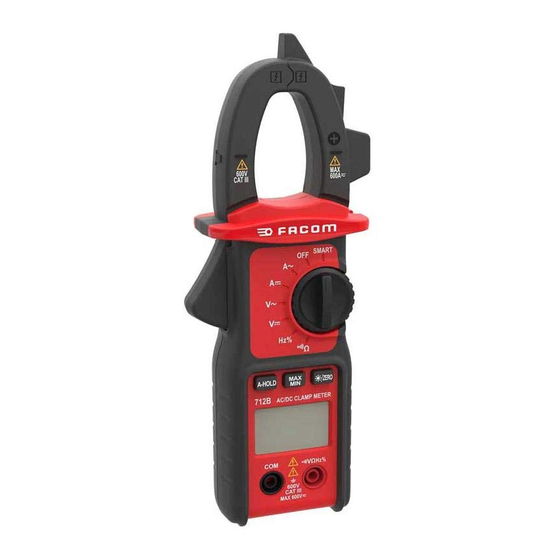
    3. Description 3.1 Panel frontal kHz% %NCV AUTO NU-712B_0618 7 langues.indd 71 22/06/2018 11:51:02...
  • Página 72 1. Pinza amperimétrica Para medir la corriente de CA/CC. 2. Barrera de seguridad Ayuda a evitar que las manos toquen los conductores mientras se mide la corriente. 3. Interruptor giratorio Se usa para seleccionar la función y el rango. 4. MÁX./MÍN. Pulse la tecla para mostrar el valor de lectura máximo entre los datos de medición, y aparecerá...
  • Página 73: Descripción

    3.2 Pantalla SÍMBOLO DESCRIPCIÓN AUTO Rango automático Voltaje/corriente de CA Voltaje/corriente de CC Batería baja Porcentaje (ciclo de servicio) Hercios (frecuencia) Voltios (voltaje) Amperios (corriente) Ω, kΩ, MΩ Ohms (resistencia) Continuidad Retención de pantalla Indicador de polaridad (negativa) NU-712B_0618 7 langues.indd 73 22/06/2018 11:51:02...
  • Página 74: Usar El Medidor

    4. Usar el medidor 4.1 Medición con función SMART Gire el interruptor giratorio a la posición “SMART”. El modo prede- terminado es “Corriente CA”, “Corriente CC”, “Voltaje CA”, “Voltaje CC”, “Resistencia” o “Continuidad”. Conecte los cables de prueba en el circuito o la carga que vaya a medir. El resultado aparecerá automáticamente en la pantalla LCD.
  • Página 75: Resistencia

    1. Inserte el cable de prueba rojo en el conector “INPUT (Entrada)” y el cable negro en el conector “COM”. 2. Gire el interruptor giratorio a la posición “ ”. Conecte los cables de prueba en el circuito o la carga que vaya a medir. 3.
  • Página 76: Continuidad

    A veces el valor del reóstato y la resistencia medida difieren. Esto se debe a que la corriente de prueba de salida del medidor atraviesa todos los caminos posibles entre los conductores. Para mediciones de baja resistencia, acorte los cables de prueba y registre la resistencia mostrada.
  • Página 77: Especificaciones Generales

    5. Especificaciones 5.1 Especificaciones generales • Potencia de seguridad: CAT III 600V • Altura de funcionamiento máx.: 2000m • Temperatura de funcionamient: 0~40 °C, HR <80 % • Temperatura de almacenamiento: -10~60 °C, HR <70 % (sin pila) • Coeficiente: Precisión 0.1/°C •...
  • Página 78 5.2.1 Voltaje de CC Rango Resolución Precisión 0.01V ± (0.5 % de lectura + 3 dígitos) 0.1V 600V - Impedancia de entrada: 10 MΩ - Protección contra sobrecargas: 600 V CC o CA rms - Voltaje máx. de entrada: 600 V CC NOTA: la medida mínima del voltaje de CC y de voltaje de CA es >=1.
  • Página 79: Resolución

    NOTA: Solo cuando el valor de corriente es superior a 0.2 A, el medidor muestra su valor de frecuencia. NOTA: Cuando el medidor detecta voltaje o resistencia en el cambio de corriente de CA, la pantalla LCD muestra «Err». 5.2.4 Corriente de CC Rango Resolución Precisión...
  • Página 80: Frecuencia (V Posición)

    5.2.7 Frecuencia (V posición) Rango Resolución Precisión 60Hz 0.1Hz ± (1.0 % de lectura + 5 dígitos) 600Hz 3kHz 10Hz - Rango de medición: 40~3 kHz - Rango de voltaje de entrada: ≥1V CA rms (la frecuencia medida aumenta a medida que aumenta el voltaje de entrada. - Protección contra sobrecargas: 600 V CC o CA rms 5.2.8 Ciclo de servicio Rango...
  • Página 81: Sustituir Las Pilas

    Utilice un paño húmedo y una pequeña cantidad de detergente para limpiar el medidor periódicamente. No use productos abra- sivos ni disolventes. Si los conectores de entrada están sucios o húmedos pueden afectar las lecturas. Para limpiar los conectores de entrada: 1.
  • Página 82: Sustituir Los Cables De Prueba

    Por favor, no lo tire en el depósito de basura, consulte con su municipio en busca de instalaciones de reciclaje en su área. Stanley Black & Decker France 62 CHEMIN DE LA BRUYÉRE 69570 DARDILLY, FRANCE www.facom.com NU-712B_0618 7 langues.indd 82 22/06/2018 11:51:02...
  • Página 83 SOMMARIO 1. Premessa ................84 2. Informazioni relative alla sicurezza........84 2.1 Precauzioni 2.2 Simboli di sicurezza 3. Descrizione................87 3.1 Pannello frontale 3.2 Display 4. Uso del tester...............90 4.1 Misurazione con funzione Smart 4.2 Spegnimento automatico 4.3 Tensione DC 4.4 Tensione AC 4.5 Corrente AC 4.6 Corrente DC 4.7 Resistenza...
  • Página 84: Premessa

    1. Premessa AVVERTENZA Assicurarsi di leggere e seguire tutte le procedure di sicurezza per evitare scosse elettriche e lesioni alle persone. Questo tester è un multimetro digitale a pinza portatile dotato di display, sicuro e affidabile nonostante le sue dimensioni ridotte. Esso è...
  • Página 85: Precauzioni

    I simboli di avvertenza che compaiono nel manuale avvisano gli utilizzatori di situazioni potenzialmente pericolose. Le precauzioni hanno lo scopo di prevenire danni allo strumento o all’oggetto che si sta testando da parte dell’utilizzatore. 2.1 Precauzioni Al fine di evitare possibili scosse elettriche, lesioni a persone o danni al tester, osservare le precauzioni elencate di seguito: Prima dell’uso verificare che l’isolamento o i fili dei conduttori del tester non siano danneggiati.
  • Página 86: Simboli Di Sicurezza

    15. Prima di passare da una funzione all’altra, rimuovere i conduttori dal circuito. 16. La normale funzione del prodotto può essere disturbata da forti interferenze elettromagnetiche. In tal caso, resettare semplicemente il prodotto per riprendere il normale funzionamento seguendo il manuale di istruzioni. Nel caso in cui non sia possibile riprendere la funzione, si prega di utilizzare il prodotto in un’altra posizione.
  • Página 87: Descrizione

    3. Descrizione 3.1 Pannello frontale kHz% AUTO %NCV NU-712B_0618 7 langues.indd 87 22/06/2018 11:51:03...
  • Página 88 1. Pinza corrente Misura la corrente AC/DC. 2. Riparo di sicurezza Aiuta a evitare di toccare con le mani i conduttori mentre si misura la corrente. 3. Manopola di selezione Usata per selezionare la funzione e l’intervallo di misura. 4. MAX/MIN Premere il tasto per visualizzare il valore massimo tra i dati misurati.
  • Página 89: Display

    3.2 Display SIMBOLO DESCRIZIONE AUTO Auto-range Tensione/Corrente AC Tensione/Corrente DC Livello di carica batterie basso Percentuale (ciclo di lavoro utile) Hertz (frequenza) Volt (tensione) Amp (Corrente) Ohm (resistenza) Ω, kΩ, MΩ Continuità Mantenimento sul display Indicatore della polarità (negativa) NU-712B_0618 7 langues.indd 89 22/06/2018 11:51:03...
  • Página 90: Uso Del Tester

    4. Uso del tester 4.1 Misurazione con funzione Smart Ruotare la manopola di selezione in posizione «SMART». La mo- dalità predefinita è «AC Current» (Corrente AC), «DC Current” (Cor- rente DC), «AC Voltage» (Tensione AC), «DC Voltage” (Tensione DC), «Resistance» (Resistenza) o «Continuity» (Continuità). Collegare i conduttori di prova al circuito o al carico da sottoporre a misura- zione.
  • Página 91: Tensione Ac

    4.4 Tensione AC 1. Inserire il conduttore di prova rosso nella presa d’«Ingresso» e quello nero nella presa «COM». 2. Ruotare la manopola di selezione in posizione « ». Collegare i conduttori di prova al circuito o al carico da sottoporre a misurazione.
  • Página 92: Resistenza

    4.7 Resistenza 1. Togliere tensione e scaricare i condensatori sul circuito sotto posto a verifica. 2. Inserire il conduttore di prova rosso nella presa d’«Ingresso» e quello nero nella presa «COM». Ω». 3. Ruotare la manopola di selezione in posizione « Collegare i conduttori di prova al circuito da sottoporre a misurazione.
  • Página 93: Frequenza/Ciclo Di Lavoro Utile

    AVVERTENZA Per evitare lesioni alle persone o danni al tester assicurarsi di disattivare completamente l’alimentazione e scaricare tutti i condensatori prima di misurare la continuità. 4.9 Frequenza/Ciclo di lavoro utile 1. Inserire il conduttore di prova rosso nella presa d’«Ingresso» e quello nero nella presa «COM».
  • Página 94: Specifiche Tecniche

    • Alimentazione: 3 batterie AAA da 1.5 V • Dimensioni: 215 mm x 79 mm x 39 mm • Peso: 195 g • Apertura max. pinza: 26 mm 5.2 Specifiche tecniche Accuratezza: ± (% lettura + cifre), garanzia di 1 anno. Temp.
  • Página 95 5.2.3 Corrente AC Range Risoluzione Accuratezza 0.01A ± (2,5% lettura + 8 cifre) 200A 0.1A 600A ± (3,0% lettura +10 cifre) - Range di frequenza: 45~65 Hz - Corrente d’ingresso max: fino a 600 A per non più di 60 secondi. - Risposta: media;...
  • Página 96: Manutenzione

    5.2.6 Continuità Range Funzione Se il valore della resistenza misurato è inferiore a 40 Ω, l’avvisatore acustico del tester emette un suono. - Tensione circuito aperto: circa 0,4 V - Protezione da sovraccarichi: 250 V DC o AC RMS 5.2.7 Frequenza (posizione V ) Range Risoluzione Accuratezza...
  • Página 97: Manutenzione Generale

    6.1 Manutenzione generale In questo capitolo sono riportati i principi fondamentali della manu- tenzione, comprendenti la pulizia e la sostituzione delle batterie. Non tentare in alcun modo di riparare o tarare il tester a meno che si sia una persona esperta. AVVERTENZA Rimuovere i conduttori di prova dal tester prima del vano batterie per evitare danni o lesioni a persone.
  • Página 98: Sostituzione Dei Conduttori

    Non smaltire insieme ai rifiuti domestici ma acquisire informazioni in merito agli impianti di riciclaggio presenti nella vostra area. Stanley Black & Decker France 62 CHEMIN DE LA BRUYÉRE 69570 DARDILLY, FRANCE www.facom.com NU-712B_0618 7 langues.indd 98 22/06/2018 11:51:04...
  • Página 99 ÍNDICE 1. Introdução .................100 2. Informações de segurança..........100 2.1 Precauções 2.2 Símbolos de segurança 3. Descrição................103 3.1 Painel dianteiro 3.2 Visor 4. Utilizar o medidor..............106 4.1 Medição da função inteligente 4.2 Desligar automaticamente 4.3 Tensão CC 4.4 Tensão CA 4.5 Corrente CA 4.6 Corrente CC 4.7 Resistência 4.8 Continuidade...
  • Página 100: Introdução

    1. Introdução ATENÇÃO Leia com atenção e respeite todos os procedimentos de segurança para evitar choque eléctrico e/ou ferimentos. O medidor é uma pinça amperimétrica digital portátil dígitos segu- ra, fiável, mas pequena. Com capacidade para medir corrente CA/ CC, tensão CA/CC, resistência e continuidade, é ideal tanto para utilizadores domésticos como profissionais.
  • Página 101 As precauções servem para evitar que o utilizador danifique o instrumento ou o objecto de teste. 2.1 Precauções Para evitar um possível choque eléctrico, ferimentos ou danos no medidor, respeite o seguinte: Verifique se os fios de prova apresentam danos no isolamento ou nos cabos antes de utilizar o equipamento.
  • Página 102: Símbolos De Segurança

    basta repor o equipamento para retomar o funcionamento normal, de acordo com o manual de instruções. Se não for possível retomar o funcionamento, utilize o equipamento noutra localização. 2.2 Símbolos de segurança Instruções importantes de segurança. Leia o manual. É permitida a aplicação perto de e a remoção de condutores sob tensão PERIGOSOS SEM ISOLAMENTO.
  • Página 103: Painel Dianteiro

    3. Descrição 3.1 Painel dianteiro kHz% %NCV AUTO NU-712B_0618 7 langues.indd 103 22/06/2018 11:51:06...
  • Página 104 1. Pinça amperimétrica Para medir tensão CA/CC. 2. Barreira de segurança Impede que as mãos toquem nos condutores quando mede corrente. 3. Interruptor rotativo Utilizado para seleccionar funções e intervalos. 4. MÁX./MÍN. Pressione a tecla para mostrar o valor máximo de leitura dos dados de medição, e o símbolo “MÁX.”...
  • Página 105 3.2 Visor SÍMBOLO DESCRIÇÃO AUTO Alcance automático Tensão/corrente CA Tensão/corrente CC Pilha fraca Percentagem (ciclo de funcionamento) Hertz (frequência) Volts (tensão) Amps (corrente) Ω, kΩ, MΩ Ohms (resistência) Continuidade Fixar visor Indicador de polaridade (negativo) NU-712B_0618 7 langues.indd 105 22/06/2018 11:51:06...
  • Página 106: Utilizar O Medidor

    4. Utilizar o medidor 4.1 Medição da função inteligente Coloque o interruptor rotativo na posição “INTELIGENTE”. O modo predefinido é “Corrente CA”, “Corrente CC”, “Tensão CA”, “Tensão CC”, “Resistência” ou “Continuidade”. Ligue os fios de prova no circuito ou a carga que pretende medir. Vai ser efectuada uma avaliação automática no visor LCD.
  • Página 107 4.4 Tensão CA 1. Insira o fio de prova vermelho na tomada “ENTRADA” e o fio preto na tomada “COM”. 2. Coloque o interruptor rotativo na posição “ ”. Ligue os fios de prova no circuito ou a carga que pretende medir. 3.
  • Página 108 4.7 Resistência 1. Desligue todos os condensadores de potência e de descarga no circuito sujeito a teste. 2. Insira o fio de prova vermelho na tomada “ENTRADA” e o fio preto na tomada “COM”. Ω”. Ligue os fios 3. Coloque o interruptor rotativo na posição “ de prova no circuito que pretende medir.
  • Página 109: Especificações Gerais

    ATENÇÃO Para evitar ferimentos ou danos no medidor, certifique-se de que desliga todas as fontes de energia e descarrega todos os condensadores antes de medir a continuidade. 4.9 Frequência/ciclo de funcionamento 1. Insira o fio de prova vermelho na tomada “ENTRADA” e o fio preto na tomada “COM”.
  • Página 110: Especificações Técnicas

    5.2 Especificações técnicas Precisão: ±(% de leitura + dígitos), garantia de 1 ano. Temp. de ambiente: 18 °C~28 °C, humidade: < 75 %. Coeficiente da temperatura: 0,1 de precisão/°C (0 °C~18 °C ou 28 °C~40 °C). 5.2.1 Tensão CC Gama Resolução Rigor 0.01V...
  • Página 111 5.2.3 Corrente CA Gama Resolução Rigor 0.01A ±(2,5 % de leitura + 8 dígitos) 200A 0.1A 600A ±(3,0 % de leitura + 10 dígitos) - Gama de frequências: 45 Hz~65 Hz. - Corrente máxima de entrada: até 600 A durante um período não superior a 60 segundos.
  • Página 112: Ciclo De Funcionamento

    5.2.6 Continuidade Gama Função Se a resistência medida for inferior a 40 Ω, é emitido um sinal sonoro do medidor. - Tensão em circuito aberto: cerca de 0,4 V. - Protecção contra sobrecargas: 250 V CC ou CA RMS. 5.2.7 Frequência (posição V) Gama Resolução Rigor...
  • Página 113: Substituir As Pilhas

    ATENÇÃO Para evitar danos ou ferimentos retire os fios de prova do medidor antes de abrir a cobertura da pilha. Use um pano húmido e uma pequena quantidade de detergente para limpar o medidor com regularidade. Não utilize solventes abrasivos ou químicos. Os conectores de entradas sujos ou molhados podem afectar as medições.
  • Página 114: Substituir Os Fios De Prova

    Não deite para o lixo e verifique junto das autoridades locais quais as instalações de reciclagem existentes na sua área. Stanley Black & Decker France 62 CHEMIN DE LA BRUYÉRE 69570 DARDILLY, FRANCE www.facom.com NU-712B_0618 7 langues.indd 114 22/06/2018 11:51:06...
  • Página 115 • Kompletní návod k použití je k dispozici na webových stránkách www.facom.com. • Versiunea completă a notiței este disponibilă pe situl INTERNET www.facom.com • Полная версия инструкции доступна на сайте www.facom. com. NU-712B_0618 7 langues.indd 115 22/06/2018 11:51:06...
  • Página 116 BELGIQUE NETHERLANDS Stanley Black&Decker BVBA Stanley Black&Decker Netherlands BV Divisie Facom Facom Netherlands LUXEMBOURG Postbus 83 Egide Walschaerstraat 16 6120 AB Born 2800 Mechelen Nederland Tel 0032 15 47 39 30 Tel 0800 236 236 2 www.facom.be www.facom.nl ASIA FACOM Nordic The Stanleyworks( Shanghai) Co.,...

Tabla de contenido