Tabla de contenido
Publicidad
Idiomas disponibles
Idiomas disponibles
Enlaces rápidos
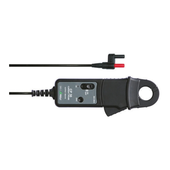
CP 30 / CP 35
AC / DC
CURRENT PROBES
Operating Instructions
SAFETY
The following symbols appear on the product:
Attention! Refer to Manual.
Application around and removal from
UNINSULATED HAZARDOUS LIVE
conductors is permitted.
Double/Reinforced Insulation.
Complies with the relevant European
standards.
Do not dispose of this product as unsorted
municipal waste. Contact a qualified
recycler for disposal.
Underwriters' Laboratory Inc. recognised
component
Read all instructions completely before
using this product.
To avoid electric shock:
• Use caution during installation and use of this product; high
voltages and currents may be present in circuit under test.
• This product must be used only by qualified personnel
practising applicable safety precautions.
• Do not use product if damaged.
• Always connect probe to display device before it is installed
around the conductor.
• Always ensure the probe is removed from any live electrical
circuit, and leads are disconnected before removing the
battery cover.
• Do not hold the probe anywhere beyond the tactile barrier
see Fig 1.
INTRODUCTION
The CP 30 / CP 35 current probe have been designed for use
with multimeters and oscilloscopes respectively for accurate,
non-intrusive measurement of AC,
DC
waveform currents.
Using advanced Hall Effect technology the CP 30 / CP 35 can
measure currents accurately with a resolution of 1mA from
5mA to 30 Amps over the frequency range of DC to 100 kHz.
These features make it a powerful tool for use in inverters,
switch mode power supplies, industrial controllers and other
applications requiring current measurement and/or waveform
analysis.
SPECIFICATION
1. Electrical data
(All accuracies stated at 23° C ± 1° C)
Nominal current In...................
Measuring range.....................
Overload capacity...................
Overall DC accuracy...............
Resolution................................
Typical output noise level.....
Gain variation..........................
Output sensitivity.....................
Frequency range.....................
di/dt response..........................
Response time.........................
Working voltage.......................
2. General data
Operating temperature............
Storage temperature with:
Battery removed......................
Power supply...........................
Battery life...............................
Load impedance (minimum)...
Conductor size........................
and complex
Weight....................................
Output cable and connectors
20 AC
or DC
RMS
0 to ±30 A
500A (60s)
±1% of reading ±2mA
±1mA
200µV r.m.s.
±0.01% of reading/° C
100mV/A
DC to 20kHz (CP 30)
DC to 100kHz (CP 35)
(0.5dB)
20A/µs
> 1µs
300V AC
or DC
RMS
0° C to +50° C
-20° C to +85° C
9 V Alkaline battery
PP3,
MN
1604
or
IEC6LR61
30 hours typical
> 100kΩ and ≤ 100pF
25 mm diameter
320 g.
1.5
m
long
coax
terminated with 4mm
safety plugs (CP 30)
2
m
long
coax
terminated with a safety
BNC
connector
50
Ohms (CP 35)
Publicidad
Tabla de contenido

Manuales relacionados para GMC-I PRO SyS CP 30

Resumen de contenidos para GMC-I PRO SyS CP 30
-
Página 7: Especificaciones
30 horas Impedancia de carga (mín.)……… > 100kΩ y ≤ 100pF La sonda CP 30 / CP 35, en combinación con un multímetro u osciloscopio, permite medir corrientes tipo AC, DC y Tamaño de conductores....25 mm de diámetro corrientes que presentan formas de onda complejas de una manera muy fiable y exacta. -
Página 8: Desconexión Automática
INSTRUCCIONES DE USO EN 61010-1:2001 Frecuencia (Hz) EN 61010-2-032:2002 1000 10000 100000 EN 61010-031:2002 +A1:2008 Activar la sonda 300V Cat III, nivel de contaminación 2 Al activar la sonda, se ilumina el LED verde. Al alcanzar las baterías un nivel de carga insuficiente para el servicio normal, Normas CEM el LED aparace parpadeando para avisar al operario.