Ingersoll Rand 2934P2 Manual De Funcionamento
Tabla de contenido
Enlaces rápidos
OPERATION AND MAINTENANCE MANUAL
TPD1362
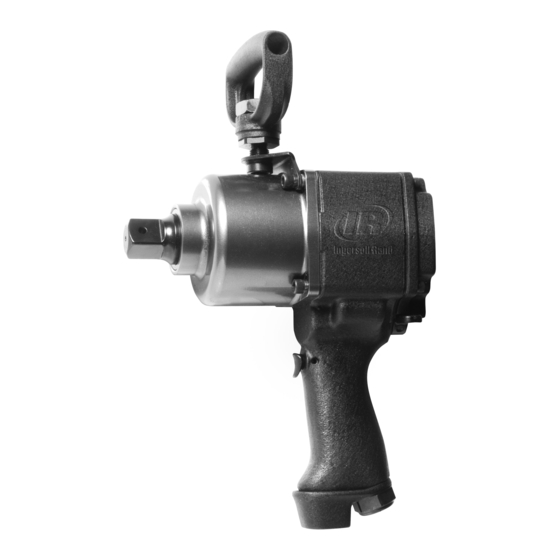
MODELS 2934P2 AND 2940P2 SUPER DUTY IMPACTOOLS
Models 2934P2 and 2940P2 Impactools are designed for use in structural fabrication, machinery
maintenance, railroad maintenance, pipe and valve flange applications and installation of lag
screws.
Ingersoll–Rand is not responsible for customer modification of tools for applications on which
Ingersoll–Rand was not consulted.
IT IS THE RESPONSIBILITY OF THE EMPLOYER TO PLACE THE INFORMATION
FAILURE TO OBSERVE THE FOLLOWING WARNINGS COULD RESULT IN INJURY.
PLACING TOOL IN SERVICE
Always operate, inspect and maintain this tool in
accordance withAmerican National Standards
Institute Safety Code for Portable Air Tools
(ANSI B186.1).
For safety, top performance, and maximum durability
of parts, operate this tool at 90 psig (6.2 bar/620 kPa)
maximum air pressure at the inlet with 3/4" (19 mm)
inside diameter air supply hose.
Always turn off the air supply and disconnect the air
supply hose before installing, removing or adjusting
any accessory on this tool, or before performing any
maintenance on this tool.
Do not use damaged, frayed or deteriorated air hoses
and fittings.
Be sure all hoses and fittings are the correct size and
are tightly secured. See Dwg. TPD905–1 for a typical
piping arrangement.
Always use clean, dry air at 90 psig (6.2 bar/620 kPa)
maximum air pressure. Dust, corrosive fumes and/or
excessive moisture can ruin the motor of an air tool.
Do not lubricate tools with flammable or volatile
liquids such as kerosene, diesel or jet fuel.
Do not remove any labels. Replace any damaged label.
USING THE TOOL
Always wear eye protection when operating or
performing maintenance on this tool.
Always wear hearing protection when operating this
tool.
The use of other than genuine Ingersoll–Rand replacement parts may result in safety hazards, decreased tool performance, and
increased maintenance, and may invalidate all warranties.
Repairs should be made only by authorized trained personnel. Consult your nearest Ingersoll–Rand Authorized Servicenter.
Refer All Communications to the Nearest
Ingersoll–Rand Office or Distributor.
Ingersoll–Rand Company 1999
Printed in U.S.A.
IMPORTANT SAFETY INFORMATION ENCLOSED.
READ THIS MANUAL BEFORE OPERATING TOOL.
IN THIS MANUAL INTO THE HANDS OF THE OPERATOR.
for
Keep hands, loose clothing and long hair away from
rotating end of tool.
Note the position of the reversing lever before
operating the tool so as to be aware of the direction of
rotation when operating the throttle.
Anticipate and be alert for sudden changes in motion
during start up and operation of any power tool.
Keep body stance balanced and firm. Do not
overreach when operating this tool. High reaction
torques can occur at or below the recommended air
pressure.
Tool shaft may continue to rotate briefly after throttle
is released.
Air powered tools can vibrate in use. Vibration,
repetitive motions or uncomfortable positions may be
harmful to your hands and arms. Stop using any tool
if discomfort, tingling feeling or pain occurs. Seek
medical advice before resuming use.
Use accessories recommended by Ingersoll–Rand.
Use only impact sockets and accessories. Do not use
hand (chrome) sockets or accessories.
Impact wrenches are not torque wrenches.
Connections requiring specific torque must be
checked with a torque meter after fitting with an
impact wrench.
This tool is not designed for working in explosive
atmospheres.
This tool is not insulated against electric shock.
03539418
Form P7071
Edition 5
March, 1999
F
E
P
Tabla de contenido

Manuales relacionados para Ingersoll Rand 2934P2


Resumen de contenidos para Ingersoll Rand 2934P2
- Página 1 OPERATION AND MAINTENANCE MANUAL TPD1362 MODELS 2934P2 AND 2940P2 SUPER DUTY IMPACTOOLS Models 2934P2 and 2940P2 Impactools are designed for use in structural fabrication, machinery maintenance, railroad maintenance, pipe and valve flange applications and installation of lag screws. Ingersoll–Rand is not responsible for customer modification of tools for applications on which Ingersoll–Rand was not consulted.
- Página 2 Power Adjustment in the Forward Direction an impact wrench. 1. While facing the back of the Impactool, push the Models 2934P2/2940P2 Impactools are equipped with a Reverse Lever to the extreme right position. combination power regulator/reverse valve designed to 2. Using a screwdriver, rotate the Power Regulator so provide power adjustment while maintaining full power in the that the slot aligns with the desired power calibration.
-
Página 3: Placing Tool In Service
AIR TOOL INLET SIZE Unit: For USA – No. C31–06–G00 SYSTEM For Model 2934P2 Before starting the tool and after each eight hours of TOOL operation, unless the air line lubricator is used, unscrew the Oil Chamber Plug and fill the chamber with Ingersoll–Rand LUBRICATOR No. -
Página 4: Utilisation De L'outil
MODÈLES 2934P2 ET 2940P2 NOTE Les clés à chocs 2934P2 et 2940P2 sont destinées aux travaux de fabrication structurelle, à l’entretien des machines, à la maintenance des vois ferrées, aux applications de tuyauteries et de flasques et à l’installation des grosses vis à bois à tête carrée. -
Página 5: Le Non Respect Des Avertissements Suivants Peut Causer Des Blessures
Réglage de la puissance dans le sens avant avec une clé à chocs. Les clés à chocs Modèles 2934P2 et 2940P2 sont équipées 1. En faisant face à l’arrière de l’outil, pousser la soupape d’un ensemble combiné régulateur de puissance/soupape d’inversion à... -
Página 6: Mise En Service De L'outil
RÉSEAU D’AIR recommandons l’emploi du filtre–régulateur–lubrificateur COMPRIMÉ suivant : USA – No. C31–06–G00 Pour le Modèle 2934P2 VERS L’OUTIL Avant de mettre l’outil en marche et toutes les huit heures PNEU- de fonctionnement, si un lubrificateur de ligne n’est pas MATIQUE utilisé, déposer le bouchon de la chambre d’huile et remplir... -
Página 7: Uso De La Herramienta
LLAVES DE IMPACTO INDUSTRIALES MODELOS 2934P2 Y 2940P2 NOTA Las Llaves de Impacto Serie 2934P2 y 2940P2 están diseñadas para usar en la fabricación de estructuras, mantenimiento de maquinaria, mantenimiento de ferrocarriles, aplicaciones de bridas de tubos y válvulas e instalación de tirafondos. -
Página 8: Etiquetas De Aviso
1. Mientras está de cara a la parte trasera de la Llave de fijación con una llave de impacto. Impacto, empuje la Palanca de Inversión completamente Las Llaves de Impacto Modelos 2934P2/2940P2 están hacia la derecha. equipadas con una válvula reguladora/invertidora de potencia 2. -
Página 9: Para Poner La Herramienta En Servicio
Filtro–Lubricador–Regulador: AL SISTEMA NEUM TICA NEUM TICO USA– Nº. C31–06–G00 Para Modelo 2934P2 A LA Antes de usar la Herramienta y después de cada ocho HERRA– horas de uso, a menos que se use un lubricante de línea de MIENTA aire, desenrosque el Tapón de Cámara de Aceite y llene dicha... -
Página 10: Usando A Ferramenta
PARA TRABALHOS SUPER MODELOS 2934P2 E 2940P2 AVISO As Ferramentas de Impacto Séries 2934P2 e 2940P2 são concebidas para uso em fabricas de estructuras, manutenção de maquinaria, manutenção de ferrovias, aplicações de flanges de tubos e válvulas e instalação de parafusos de madeira. - Página 11 Alavanca de Reversão para a posição, na extrema direita. As Ferramentas de Impacto Modelos 2934P2/2940P2 são 2. Usando uma chave de fendas, gire o Regulador de equipadas com uma combinação de válvulas de Potência de modo a que o orifício fique alinhado com o reversão/reguladora de potência projectadas para fornecer...
-
Página 12: Colocando A Ferramenta Em Funcionamento
Filtro–Lubrificador–Regulador: ENTRADA DA FERRAMENTA PNEUM TICA PARA SISTEMA DE AR USA – C31–06–G00 Para o Model 2934P2 Antes de operar a Ferramenta e depois de oito horas de PARA operação, ao menos que esteja usando um lubrificador de ar FERRAMENTA PNEUM TICA de linha, remova o Bujão da Câmara de Óleo e preencha a... - Página 13 (Dwg. TPA1337–1)
- Página 14 PART NUMBER FOR ORDERING PART NUMBER FOR ORDERING 1 Motor Housing Assembly ..2934P–A40A 2940P–A40 Throttle Valve Assembly ..––– 293–A302 Inlet Bushing ... . . 2934P–465 2940P–A565 Throttle Valve Bushing Washer .
-
Página 15: Tabla De Contenido
PART NUMBER FOR ORDERING PART NUMBER FOR ORDERING Silencer Cover ....––– 2940P–240 Housing Cover Gasket ..2934–283 2934–283 Silencer Cover Screws (3) ..––– 401–638 Motor Clamp Washer . - Página 16 SPLINE DRIVE ANVIL (Dwg. TPA1338)
-
Página 17: Washer (4)
PART NUMBER FOR ORDERING PART NUMBER FOR ORDERING 61 Side Spade Handle Bracket ....2934–364 Socket Retainer ......RR10015S 62 Side Spade Handle . -
Página 18: Setting The Power Regulator
SETTING THE POWER REGULATOR Models 2934P/2940P Impactools are equipped with a Power Adjustment in the Forward Direction combination power regulator/reverse valve designed to provide power adjustment while maintaining full power in While facing the back of the Impactool, push the the reverse direction. -
Página 19: Cylinder
MAINTENANCE SECTION Hold the Hammer Frame firmly and, without With the Impactool turned toward you, and the Trigger disturbing the Hammers, gently lift the Anvil, (16) secured by an alternate means, use a Pin Punch to simultaneously rotating it counterclockwise about 1/8 drive out the Trigger Retaining Pin (18). -
Página 20: Cylinder Dowel
MAINTENANCE SECTION 8. Follow the Plunger with the Throttle Valve (7) spring Using a sleeve that will contact only the outer ring of seat end facing up. the Rear Rotor Bearing (54), press the bearing into the 9. Place the Throttle Valve Spring (6), small end first on Rear End Plate (55). - Página 21 MAINTENANCE SECTION Assembly of the Impact Mechanism Replace Hammer Pins (66). Examine the base of the Anvil (68 or 69) and note its contour. While looking down through the Hammer Frame, swing the top Hammer to its full extreme one way or the other until you can match the contour of the TOP HAMMER Anvil.
-
Página 22: Troubleshooting Guide
MAINTENANCE SECTION TROUBLESHOOTING GUIDE Trouble Probable Cause Solution Low power Dirty Inlet Bushing or Air Using a clean, suitable, cleaning solution, in a well Strainer Screen and/or Exhaust ventilated area, clean Air Strainer Screen, Inlet Silencer Bushing and Exhaust Silencer. Worn or broken Vanes Replace complete set of Vanes. - Página 23 NOTES...