NuTone HUGGER Serie Manual De Instrucciones
Tabla de contenido
Idiomas disponibles
Idiomas disponibles
Enlaces rápidos
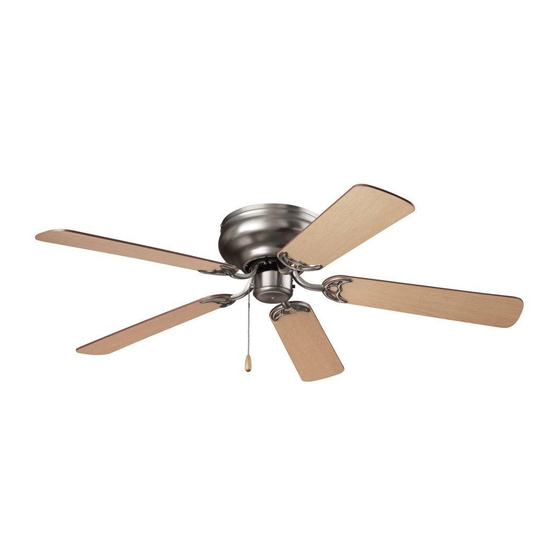
HUGGER SERIES
CEILING FANS
READ AND SAVE THESE INSTRUCTIONS
WARNING
TO REDUCE THE RISK OF FIRE, ELECTRICAL SHOCK, OR INJURY
TO PERSONS, OBSERVE THE FOLLOWING:
1. Use this unit only in the manner intended by the manufacturer. If
you have questions, contact the manufacturer at the address or
telephone number listed in the warranty.
2. Before servicing or cleaning unit, or installing a light kit, switch power
off at service panel and lock service panel to prevent power from
being switched on accidentally. When the service disconnecting
means cannot be locked, securely fasten a prominent warning
device, such as a tag, to the service panel.
3. Installation work and electrical wiring must be done by a qualified
person(s) in accordance with all applicable codes and standards,
including fire-rated construction codes and standards.
4. When cutting or drilling into wall or ceiling, do not damage electrical
wiring and other hidden utilities.
5. This unit must be grounded.
6. Do not use this fan with any solid-state fan speed control device.
7. Most outlet boxes commonly used for the support of lighting fixtures
are not acceptable for fan support and may need to be replaced,
consult a qualified electrician if in doubt.
Use only UL Listed outlet boxes marked "FOR FAN SUPPORT".
The outlet box and support structure must be securely mounted and
capable of reliably supporting a minimum of 50 pounds. Use only
the two steel screws (and lock washers) provided with the outlet box
for mounting the ceiling fan to the outlet box The outlet box must
not twist or work loose. DO NOT USE PLASTIC OUTLET BOXES.
8. After marking electrical connections, spliced conductors should
be turned upward and pushed carefully up into outlet box. The
wires should be spread apart with the grounded conductor and the
equipment-grounding conductor on one side of the outlet box.
9. Electrical diagrams are for reference only. Light kits that are not
packed with the fan must be UL Listed and marked suitable for use
with the model fan you are installing. Switches must be UL General
Use Switches. Refer to the instructions packaged with the light kits
and switches for proper assembly.
10. After installation is complete, make sure that all connections are
secure to prevent the fan from falling. Make sure all wire connections
are secure, and that there are no exposed conductor strands.
11. Do not use water or detergents when cleaning the fan or fan blades.
A dry dust cloth or lightly dampened cloth will be suitable for most
cleaning.
MODELS CFH52BS • CFH52PB • CFH52RB • CFH52WH
CAUTION
TO REDUCE THE RISK OF PERSONAL INJURY, OBSERVE THE
FOLLOWING:
1. To avoid motor bearing damage and noisy and/or unbalanced
impellers, keep drywall spray, construction dust, etc. off power unit.
2. The fan must be mounted with at least 7 feet of clearance between
fan blades and floor.
3. Make sure that your installation will not allow the fan to come into
contact with any adjacent obstacles such as doors, hanging lamps,
etc.
4. If you are installing more than one ceiling fan, do not mix the blade
sets.
5. Do not bend the blade brackets.
6. Do not operate reversing switch while fan blades are in motion.
Fan must be turned off and blades stopped before reversing blade
direction.
7. Do not insert objects in between rotating fan blades.
8. Be careful when working around or cleaning the fan.
9. Please read specification label on product for further information
and requirements.
WEIGHT OF FAN
The weight of your fan is 15.2 lbs.. The weights of light kits, down rods,
and ceiling adapters are listed in the instructions packed with those
accessories.
INSTALLER:
Leave this manual with the
homeowner.
HOMEOWNER:
Use and care instructions on
pages 6 & 7.
Page 1
Tabla de contenido

Manuales relacionados para NuTone HUGGER Serie


Resumen de contenidos para NuTone HUGGER Serie
-
Página 9: Ventiladores De Techo De La Serie Hugger
MODELOS CFH52BS • CFH52PB • CFH52RB • CFH52WH Página 9 VENTILADORES DE TECHO DE LA SERIE HUGGER LEA Y GUARDE ESTAS INSTRUCCIONES ADVERTENCIA PRECAUCIÓN PARA REDUCIR EL RIESGO DE INCENDIO, DESCARGA ELÉCTRICA PARA REDUCIR EL RIESGO DE LESIONES, SIGA LAS INDICACIONES O LESIONES, SIGA LAS INDICACIONES QUE SE ENUMERAN A QUE SE ENUMERAN A CONTINUACIÓN: CONTINUACIÓN:... -
Página 10: Herramientas Ymateriales Requeridos
MODELOS CFH52BS • CFH52PB • CFH52RB • CFH52WH Página 10 CONTENIDO Desempaque su ventilador y verifique que el contenido esté completo. El paquete debe incluir lo siguiente: A - Juego de paletas (5) B - Soporte de montaje C - Conjunto del motor del ventilador D - Carcasa del motor E - Juego de soportes de paletas F - Herrajes del paquete Cadenilla de tiro y dispositivo de seguridad CAJA DE DISTRIBUCIÓN FIGURA 1 HERRAMIENTAS Y MATERIALES REQUERIDOS DESTORNILLADOR DESTORNILLADOR... -
Página 11: Instalación Del Ventilador
MODELOS CFH52BS • CFH52PB • CFH52RB • CFH52WH Página 11 INSTALACIÓN DEL VENTILADOR 1. Sujete el soporte de montaje a la caja de distribución con los dos tornillos y las arandelas suministrados con la caja de distribución. (Fig. 4). Para un mejor rendimiento, asegúrese de que el soporte de montaje esté nivelado y firmemente sujeto al techo. Probablemente deba agregar más arandelas (no incluidas) entre la caja de CAJA DE DISTRIBUCIÓN distribución y el soporte de montaje para nivelarlo. SOPORTE DE MONTAJE 2. Con cuidado, eleve el conjunto del motor del ventilador (sin las paletas) e inserte la sección "T" de la placa de la carcasa del motor en la ranura TORNILLOS del soporte de montaje, tal como se muestra en la fig. 5. FIGURA 4 CAJA DE DISTRIBUCIÓN RANURA... -
Página 12: Cableado De Conexión
MODELOS CFH52BS • CFH52PB • CFH52RB • CFH52WH Página 12 CABLEADO DE CONEXIÓN ENTRADA DE LÍNEA 120 VCA CABLE A Recuerde desconectar la alimentación eléctrica. Siga los pasos que TIERRA VERDE se indican a continuación para conectar el ventilador a la instalación eléctrica de su hogar. Utilice las tuercas para alambre suministradas con el ventilador. Sujete los conectores con cinta aislante. Asegúrese CAJA DE de que no haya hilos ni conexiones sueltos. CONEXIONES CABLE A TIERRA SI INSTALA UN KIT DE ILUMINACIÓN OPCIONAL, CONSULTE A SOPORTE DE LAS INSTRUCCIONES INCLUIDAS CON EL KIT. -
Página 13: Terminación De La Instalación
MODELOS CFH52BS • CFH52PB • CFH52RB • CFH52WH Página 13 TERMINACIÓN DE LA INSTALACIÓN 1. Lleve hacia arriba el conjunto del motor hasta su posición debajo del soporte de montaje. Asegure el soporte a la placa con los tornillos suministrados. (Fig. 9) 2. Con cuidado levante la carcasa del motor sobre el soporte de SOPORTE DE montaje, alinee los orificios correctamente y ajuste la carcasa con MOTOR... -
Página 14: Funcionamiento
MODELOS CFH52BS • CFH52PB • CFH52RB • CFH52WH Página 14 FUNCIONAMIENTO Encienda la alimentación y verifique el funcionamiento de su ventilador. CADENILLA DE TIRO DE 3 VELOCIDADES Controla la velocidad del ventilador de la siguiente manera: 1 tirón: alta, 2 tirones: intermedia, 3 tirones: baja, y 4 tirones: apagado. La configuración de las velocidades para temperaturas cálidas o frías depende de diversos factores, como el tamaño de la habitación, la altura del techo y la cantidad de ventiladores. INTERRUPTOR DESLIZANTE Controla las direcciones: adelante (interruptor hacia abajo) o reversa (interruptor hacia arriba). NOTA: Espere a que el ventilador se detenga antes de cambiar la FIGURA 12 configuración del interruptor deslizante. -
Página 15: Solución De Problemas
MODELOS CFH52BS • CFH52PB • CFH52RB • CFH52WH Página 15 SOLUCIÓN DE PROBLEMAS PIEZAS DE SERVICIO El ventilador no se enciende. 1. Verifique los fusibles o los disyuntores. CLAVE N° DE PIEZA DESCRIPCIÓN 2. Verifique las conexiones de los cables al ventilador y las 1 S77000911 JUEGO DE PALETAS (INCLUYE 5) (CFH52WH) conexiones del cable del interruptor en la carcasa de interruptores. S77000912 JUEGO DE PALETAS (INCLUYE 5) (CFH52BS) PRECAUCIÓN: Asegúrese de que el interruptor principal de... -
Página 16: Periodo De Garantía
LIMITADAS, LA DURACIÓN DE CUALQUIER GARANTÍA IMPLÍCITA APLICABLE ESTÁ LIMITADA AL PERIODO ESPECIFICADO PARA LA GARANTÍA EXPRESA. Algunos estados no permiten limitaciones en la duración de una garantía implícita, así que la limitación anterior tal vez no aplique en su caso. Cualquier descripción verbal o escrita del ventilador es para el único propósito de identificarlo y no deberá considerarse como una garantía expresa. REMEDIO: Durante el periodo de garantía limitada aplicable, NuTone, a su opción, suministrará piezas de repuesto, o reparará o reemplazará, sin cargo alguno, cualquier ventilador o pieza, hasta el grado en que NuTone lo encuentre cubierto bajo esta garantía limitada y en incumplimiento de la misma. NuTone le enviará el ventilador reparado o reemplazado o las piezas de repuesto sin cargo. Usted es responsable de todos los costos de retiro, reinstalación y envío, seguro u otros cargos de flete incurridos en el envío del ventilador o la pieza a NuTone.