Viking VBBO1601 Manual De Uso Y Instalación
Ocultar thumbs Ver también para VBBO1601:

Publicidad

Idiomas disponibles

Idiomas disponibles

Enlaces rápidos

Use / Install
MANUAL
Outdoor Stainless Steel Cabinets
VBBO1601 / VBBO2602 / VBBO5160 / VBBO5260
VURO3200 / VBO1811 / VBO1830 / VSBO2402 / VTOP1810
VQBO4121 / VQBO5322 / VQBO5420 / VQBO5540 / VQWO4120 / VQWO5311

Publicidad

Tabla de contenido
loading

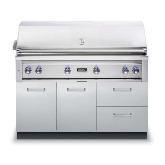
Resumen de contenidos para Viking VBBO1601

  • Página 1 Use / Install MANUAL Outdoor Stainless Steel Cabinets VBBO1601 / VBBO2602 / VBBO5160 / VBBO5260 VURO3200 / VBO1811 / VBO1830 / VSBO2402 / VTOP1810 VQBO4121 / VQBO5322 / VQBO5420 / VQBO5540 / VQWO4120 / VQWO5311...
  • Página 2 IMPORTANT - PLEASE READ AND FOLLOW •Before beginning, please read these instructions completely and carefully. •Do not remove permanently affi xed labels, warnings, or plates from product. This may void the warranty. • Outdoor stainless steel cabinets are not designed to be water tight. Water may enter cabinetry under certain conditions •The installer should leave instructions with the consumer who should retain for future reference WARNING NEVER use LP tanks inside any stainless steel cabinetry.
  • Página 3 IMPORTANT - PLEASE READ AND FOLLOW! 5. Place cabinet(s) in approximate fi nal position. Illustration #3 Level cabinets using leveling legs. If installing Install (4) Tinnerman clips two or more cabinets, use 1/2” SMS screws (provided) before fastening provided to screw them together. (See cabinets together.
  • Página 4 INSTALLATION 8. If desired, snap toe kick included with Illustration #6 each unit to front legs. (See illustration #6). Snap toe kick to front legs 9. SIDE PANEL INSTALLATION (End of Run Only) •Remove all drawers. (If applicable) • Remove all protective covering from panel and install using the #10 x 1/2” tek screws provided. (See Illustration #7) •Attach toe kick to legs (See Illustration #6).
  • Página 5 INSTALLATION 10. BACK PANEL INSTALLATION • Remove all protective covering from panel and install using the 10 x 1/2” tek screws provided. (See Illustration #8). • Attach rear toe kick to legs. (See illustration #8). NOTE: For end of the run panels, the rear, front, and side toe kicks must be modifi ed. (See illustrations #7 & #8) Illustration #8 1.
  • Página 6 (4) #10-12 cabinet screws 2. If you are installing a Viking grill on either side of the burner, there is a hole on either side of the cabinet provided in order to connect the grill to the side or power burner unit.
  • Página 7: Cleaning And Maintenance

    10. If you are installing a Viking side burner or power burner on either side of the grill, there is a hole on either side of the cabinet provided to feed the connector from the grill to the burners.
  • Página 8 DIMENSIONS OVERALL WIDTH (A) OVERALL HEIGHT OVERALL DEPTH VBBO1601 15 5/8” (39.7 cm) 34 1/2” (87.6 cm) 29 7/8” (75.9 cm) VBBO2602 26 3/8” (67.0 cm) 34 1/2” (87.6 cm) 29 7/8” (75.9 cm) VBBO5160 14 1/2” (36.8 cm) 34 1/2” (87.6 cm) 29 7/8”...
  • Página 9: Front View

    GRILL BASE DIMENSIONS Front View Opening for grill to slide into 34-1/2” (87.6 cm) Refer to chart on previous page 29-7/8” (75.9 cm) Side View 34-1/2” (87.6 cm)
  • Página 10: Service Information

    Clearly describe the problem that you are having. If you are unable to obtain the name of an authorized service agency, or if you continue to have service problems, contact Viking Range at (888) 845-4641 or write to: VIKING RANGE, LLC...
  • Página 11: Terms And Conditions

    Outdoor cabinets and all of their component parts, except as detailed below*, are warranted to be free from defective materials or workmanship in normal residential use for a period of two (2) years from the date of original retail purchase or closing date for new construction, whichever period is longer.. Viking Range, LLC, warrantor, agrees to repair or replace, at its option, any part which fails or is found to be defective during the warranty period.
  • Página 12 Viking Range, LLC 111 Front Street Greenwood, Mississippi 38930 USA (662) 455-1200 For product information, call 1-888-(845-4641) or visit the Viking Web site at vikingrange.com 068259-000 EN (051018)
  • Página 13 Manual d’Installation/ Utilisation Petits Meubles d’Exterieur VBBO1601 / VBBO2602 / VBBO5160 / VBBO5260 VURO3200 / VBO1811 / VBO1830 / VSBO2402 / VTOP1810 VQBO4121 / VQBO5322 / VQBO5420 / VQBO5540 / VQWO4120 / VQWO5311...
  • Página 14 IMPORTANT : VEUILLEZ LIRE ET APPLIQUER •Avant de commencer, veuillez lire ces instructions complètement et avec attention. • N’enlevez pas de façon permanente des étiquettes collées, des mises en garde ou des plaques de ce produit. Cela peut annuler votre garantie. •...
  • Página 15 IMPORTANT : VEUILLEZ LIRE ET APPLIQUER 5. Placez le(s) meuble(s) à peu près à leur l’illustration 3 position fi nale. Mettez le(s) de niveau avec les pieds réglables. Utilisez les vis SMS Installer 4 agrafes Tinnerman (fournies) fournies pour visser ensemble les meubles avant d’attacher les meubles ensemble (voir l’illustration 3) Fixer les meubles...
  • Página 16: Installatons En Îlots

    INSTALLATION 8. Si vous le souhaitez, encliquetez sur les l’illustration 6 pieds à l’avant la plinthe incluse avec le meuble (voir l’illustration 6). Encliquetage de plinthe sur pieds avant 9. INSTALLATION DU PANNEAU LATÉRAL (fi n de rangée uniquement) •Enlevez tous les tiroirs (s’il y a lieu). •...
  • Página 17: Installation De Plan De Travail De Fourniture Locale

    INSTALLATION 10. INSTALLATION DU PANNEAU ARRIÈRE • Enlevez tout le revêtement protecteur du panneau et montez-le en utilisant les vis tek 10 x 1/2” (1,3 cm) fournies (voir l’illustration 8). •Fixez la plinthe arrière sur les pieds (voir l’illustration 8). REMARQUE : Pour extrémités de rangée, il faut adapter les plinthes latérales, avant et arrière (voir les illustrations 7 et 8).
  • Página 18 (4) vis n° de l’encadrement. 10-12 2. Si vous installez une grille Viking sur un côté du brûleur, vous trouverez un trou sur un côté de l’encadrement fourni, afi n de raccorder la grille au brûleur électrique ou au brûleur latéral.
  • Página 19: Nettoyage Et Entretien

    à épaulement et en le repoussant par glissement. 10. Si vous installez un brûleur latéral Viking ou un brûleur électrique sur un côté de la grille, vous trouverez un trou sur un côté du meuble fourni, afi n de raccorder le connecteur de la grille aux brûleurs.
  • Página 20: Spécifications De Base

    SPÉCIFICATIONS DE BASE LARGEUR TOTALE HAUTEUR TOTALE PROFONDEUR TOTALE VBBO1601 15 5/8” 939,7 cm) 34 1/2” (87.6 cm) 29 7/8” (75.9 cm) VBBO2602 26 3/8” (67.0 cm) 34 1/2” (87.6 cm) 29 7/8” (75.9 cm) VBBO5160 14 1/2” (36.8 cm) 34 1/2”...
  • Página 21 Vue de face Ouverture pour le grill pour se glisser dans 34-1/2” (87.6 cm) Se référer au tableau sur la page précédente 29-7/8” (75.9 cm) Vue de côté 34-1/2” (87.6 cm)
  • Página 22: Informations Sur L'entretien

    • Nom du distributeur qui vous a vendu le produit Décrivez clairement votre problème. Si vous n’arrivez pas à obtenir le nom d’un centre de réparation agréé, ou si les problèmes d’entretien persistent, contactez Viking Range au 1-888-845-4641, ou écrivez à : VIKING RANGE, LLC SERVICE PRIVILÉGIÉ...
  • Página 23: Garantie Limitée De Deux Ans

    (2) ans à partir de la date d’achat d’origine ou la date d’achèvement d’une construction neuve, la période la plus longue étant à retenir. Le garant, Viking Range, LLC, réparera ou remplacera, à sa discrétion, toute pièce en panne ou défectueuse pendant la période de garantie.
  • Página 24 Viking Range, LLC 111 Front Street Greenwood, Mississippi 38930 USA (662) 455-1200 Pour des informations sur les produits, appelez le 1-888-(845-4641) ou visitez notre site web aux États-Unis au vikingrange.com 068259-000 FR (051018)
  • Página 25: Gabinetes Para Exteriores

    Manual de Uso y Instalación Gabinetes para Exteriores VBBO1601 / VBBO2602 / VBBO5160 / VBBO5260 VURO3200 / VBO1811 / VBO1830 / VSBO2402 / VTOP1810 VQBO4121 / VQBO5322 / VQBO5420 / VQBO5540 / VQWO4120 / VQWO5311...
  • Página 26: Para Instalar Los Gabinetes

    •No retire las etiquetas, advertencias o placas fi jas del producto. Esto podría invalidar la garantía. • Los gabinetes de acero inoxidable para exteriores de Viking no están diseñados como herméticos al agua. Existen algunas condiciones en las que el agua puede penetrar en los gabinetes.
  • Página 27 IMPORTANTE - POR FAVOR LEA Y CUMPLA 5. Coloque el gabinete(s) en la posición fi nal Ilustración #3 aproximada. Nivele los gabinetes utilizando Instale 4 sujetadores Tinnerman las patas de nivelación. Utilice tornillos para (suministrados) antes de unir metales, de 1/2”, suministrados para unir los los gabinetes gabinetes mediante tornillos.
  • Página 28: Instalación

    INSTALACIÓN 8. Si se desea, sujete a presión la tabla de Ilustración #6 base (incluida con cada unidad) a las patas delanteras. (Véase la ilustración #6). Sujete a presión la tabla de base a las patas delanteras 9. INSTALACIÓN DE PANEL LATERAL [Extremo del recorrido (tramo) únicamente] •Retire todas las gavetas.
  • Página 29: Instalación Del Panel Trasero

    (3.8 cm.), deben instalarse láminas de relleno a los aparatos hasta la altura apropiada. Para obtener ejemplos de instalaciones comunes, véase la Guía de Planeación para el Acero Inoxidable (Stainless Steel Planning Guide) de Viking. 12. Instale los aparatos según las instrucciones de instalación de cada aparato.
  • Página 30: Instalación Del Transformador

    1. El transformador debe estar montado dentro n.º 10 al 12 del gabinete 2. Si está instalando una parrilla Viking a cada lado de la hornilla, hay un orifi cio en cada lado del gabinete provisto para conectar la transformador parrilla al lado o a la unidad de potencia de la hornilla.
  • Página 31: Cuidado Y Mantenimiento

    10. Si está instalando una hornilla lateral u hornilla de potencia Viking a ambos lados de la parrilla, hay un orifi cio en cada lado del gabinete provisto para alimentar el conector de la parrilla a las hornillas.
  • Página 32: Especificaciones Básicas

    ESPECIFICACIONES BÁSICAS ANCHO TOTAL ALTURA TOTAL PROFUNDIDAD TOTAL VBBO1601 15 5/8” 939.7 cm) 34 1/2” (87.6 cm) 29 7/8” (75.9 cm) VBBO2602 26 3/8” (67.0 cm) 34 1/2” (87.6 cm) 29 7/8” (75.9 cm) VBBO5160 14 1/2” (36.8 cm) 34 1/2” (87.6 cm) 29 7/8”...
  • Página 33 ESPECIFICACIONES BÁSICAS Vista frontal Apertura de la parrilla se deslice 34-1/2” (87.6 cm) Refi érase a la tabla de la página anterior 29-7/8” (75.9 cm) Vista lateral 34-1/2” (87.6 cm)
  • Página 34: Información De Servicio

    Describa claramente el problema que tiene. Si no puede obtener el nombre de un centro de servicio autorizado, o si continúa teniendo problemas de servicio, póngase en contacto con Viking Range, LLC llamando al (888) 845-4641, o escriba a: VIKING RANGE, LLC...
  • Página 35: Garantía

    Range, LLC, 111 Front Street, Greenwood, Mississippi 38930, (888) 845-4641. Indique el número de modelo y de serie, así como la fecha de la compra original o la fecha de cierre de una construcción nueva. Para saber el nombre de su agencia de servicio autorizado más cercana de Viking Range, LLC llame a Viking Range, LLC.
  • Página 36 Viking Range, LLC 111 Front Street Greenwood, Mississippi 38930 USA (662) 455-1200 Para información del producto, llame al 1-888-(845-4641) o visite el sitio web de Viking en vikingrange.com 068259-000 SP (051018)

Tabla de contenido