Honeywell TL8100 Guia De Instalacion
Ocultar thumbs
Ver también para TL8100:
- Guia del usuario (13 páginas) ,
- Instrucciones de instalación (13 páginas) ,
- Guia de instalacion (4 páginas)
Tabla de contenido
Idiomas disponibles
Idiomas disponibles
Enlaces rápidos
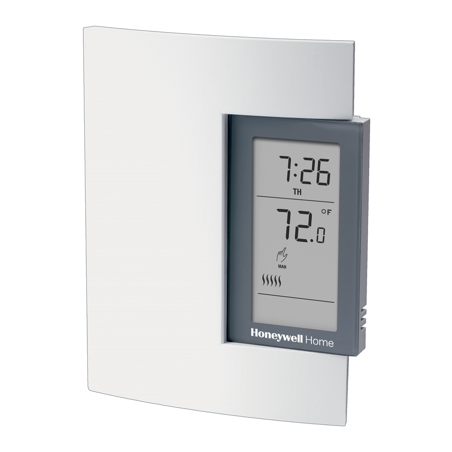
TL8100 Programmable Thermostat
1. GUIDELINES
TURN OFF POWER TO THE HEATING SYSTEM AT THE
MAIN POWER PANEL TO AVOID ELECTRICAL SHOCK.
INSTALLATION SHOULD BE CARRIED OUT BY AN
ELECTRICIAN.
• For a new installation, choose a location about 5 ft. (1.5 m)
above the floor.
• The thermostat must be installed on an inside wall.
• Avoid locations where there are air drafts (top of staircase,
air outlet), dead air spots (behind a door), direct sunlight, or
concealed chimneys or stove pipes.
2. PROCEDURE
1. Loosen the captive screw securing the front module to
the rear module as shown in Fig. 1.
2. Lift the lower part of the front module to remove it from
the rear module.
3. Loosen the captive screw holding the terminal cover
and remove the cover.
4. Pass the wires through the opening to the right of the
terminals. See Fig. 2. Secure the rear module to an
electrical box or to the wall using the supplied wall
anchors and screws.
5. Connect the wires (see section "Thermostat Wiring" on
page 2). Use 12 AWG or smaller wire. 14 AWG is rec-
ommended for line voltage, 18 AWG is recommended
for 24 VAC.
6. Install the terminal cover and tighten the screw.
7. Configure the thermostat using the switches located on
the back of the front module (see section "Thermostat
Configuration" on page 3).
8. Install the batteries (see section "Power-up" on page 4).
9. Mount the front module onto the rear module and
tighten the screw.
INSTALLATION INSTRUCTIONS
2
1
4
5
8
7
Fig. 1. Installation steps.
Fig. 2. Routing wires to thermostat.
3
6
9
M29963
SUPPLY
LOAD
PROVIDED
WIRES
M29964
69-2017EFS-01
Tabla de contenido

Manuales relacionados para Honeywell TL8100


Resumen de contenidos para Honeywell TL8100
-
Página 9: Instrucciones
TL8100 Termostato programable GUÍA DE INSTALACIÓN 1. INSTRUCCIONES CORTAR LA ALIMENTACIÓN DEL SISTEMA DE CALEFACCIÓN EN EL PANEL CENTRAL PARA EVITAR RIESGOS DE ELECTROCUCIÓN. LA INSTALACIÓN DEBE REALIZARLA UN ELECTRICISTA. • En el caso de una instalación nueva, elegir un sitio a alrededor de 1.5 m (5 ft) sobre el piso. -
Página 10: Cableado Del Termostato
TL8100 TERMOSTATO PROGRAMABLE 3. CABLEADO DEL V8043A, E TERMOSTATO TL8100 120 V CA o 240 V CA CARGA INDUCTIVA MÁXIMA DE 2 AMP TL8100 MS29965 CONECTE LOS CABLES NEGROS EN LA V8043A Fig. 3. Diagrama de cableado de un circulador de voltaje Y LOS CABLES AMARILLOS EN LA V8043E. -
Página 11: Configuración Del Termostato
TERMOSTATO ser el diferencial. • Cuando se conectan más de un TL8100 directamente a una válvula de zona o a un circulador de zona. En la Tabla 1 se muestra la configuración de los interruptores en la parte posterior del módulo frontal. - Página 12 Honeywell International Inc. 1985 Douglas Drive North Golden Valley, MN 55422 Honeywell Limited-Honeywell Limitée 35, Dynamic Drive ® Marca Registrada en los E.U.A © 2010 Honeywell International Inc. Toronto, Ontario M1V 4Z9 todos Los Derechos Reservados 69-2017EFS—01 M.S. Rev. 04-10 customer.honeywell.com...