Interlogix ATS1100 Hoja De Instalación
Tabla de contenido
Idiomas disponibles
Idiomas disponibles
Enlaces rápidos
ATS1100/1105 8-Area LCD RAS Installation
Sheet
EN DA DE ES
FI
FR
1
(1)
J2
J3
EN: Installation Sheet
Mounting the unit
Please make sure the keypad is mounted on a flat surface, in
order to prevent any incorrect tamper switch actuations.
Attach the mounting box using screws. Secure the PCB with
the screw supplied. Secure the keypad cover with the screw
supplied.
When a pry-off tamper is required, use a screw in the back of
the keypad (see Figure 1, item 2).
Connecting the keypad to a control panel
Figure 1, item 1: Refer to the ATS control panel installation
guide for instructions.
LEDs
•
Rx: LED flashes to indicate polling data is being received
on the system data bus from the ATS control panel. If the
LED does not flash the control panel is not operational or
the data bus is faulty (usually cabling).
•
Tx: LED flashes to indicate the arming station (RAS) is
replying to polling from the ATS control panel. If the Rx
(Rx0) LED flashes but the Tx (Tx0) LED does not, the
arming station (RAS) is not programmed to be polled in
the control panel or is addressed incorrectly.
© 2019 UTC Fire & Security Americas Corporation, Inc.
IT
NL NO PL PT SV
Rx
Tx
(2)
(3)
1 2 3 4
(4)
1 2 3 4
SW2
2
ON
SD
ON
1
2 3 4
1
RAS 1
ON
SD
ON
1
2 3 4
1
RAS 5
ON
SD
ON
1
2 3 4
1
RAS 9
ON
SD
ON
1
2 3 4
1
RAS 13
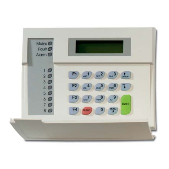
LED Indications on keypad
•
Area: 8 red LEDs illuminate when area 1–8 (or 9–16) are
armed. Will blink (armed) or flash (disarmed) on alarm.
•
Mains: Green LED illuminates if 230 VAC mains power is
available.
•
Alarm: Red LED illuminates on any alarm in an area
assigned to the keypad.
•
Fault: Yellow LED illuminates on faults in the system.
Comms connections
See Figure 1, terminal J3.
•
+12, 0V: Power supply. If the distance between the arming
station and the control panel does not exceed 100 m, then
the arming station can be powered using the Comms +
and − from the control panel. Otherwise use AUX PWR
from DGPs or an auxiliary power supply.
•
D+, D−: Data positive and data negative connection of the
data bus.
Remote units can be up to 1.5 km from the ATS control
panel.
•
IN: A request to exit button (normally open, momentary
push-button switch) can be connected across "IN" and "−".
When pressed, this button controls the request to exit
function.
•
OUT: Open collector output, 50 mA maximum. It is the first
output of the output control group that is assigned to this
arming station.
1 / 1
SW1
SD
ON
SD
ON
SD
2 3 4
1
2 3 4
1
2 3 4
RAS 2
RAS 3
RAS 4
SD
ON
SD
ON
SD
2 3 4
1
2 3 4
1
2 3 4
RAS 6
RAS 7
RAS 8
SD
ON
SD
ON
SD
2 3 4
1
2 3 4
1
2 3 4
RAS 10
RAS 11
RAS 12
SD
ON
SD
ON
SD
2 3 4
1
2 3 4
1
2 3 4
RAS 14
RAS 15
RAS 16
P/N 1052492 (ML) • REV C • ISS 24JUN19
Tabla de contenido

Resumen de contenidos para Interlogix ATS1100
- Página 5 • 3: GND (0V) • 4: +5 V Kontaktinformationen • 5: +12 V www.utcfireandsecurity.com oder www.interlogix.com Zusätzliche Funktionalität Kontaktinformationen für den Kundendienst finden Sie unter www.utcfssecurityproducts.de • Zum Anpassen des LCD-Kontrasts – Drücken Sie Menü * und oder .
-
Página 6: Conexiones Comms
• Alimentación: Cuando la alimentación de 230 V CC está SW2-4, TERM conectada, se ilumina un LED verde. OFF: No es el último dispositivo del bus de datos. • Alarma: En caso de que se produzca una alarma, sea del ON: Termina el bus de datos si esta estación RAS es el último tipo que sea, en un área asignada al teclado, se ilumina dispositivo del bus de datos.