LEGRAND Wattstopper Manual Del Usario
Ocultar thumbs
Ver también para Wattstopper:
- Manual de instrucciones (20 páginas) ,
- Manual del usuario (17 páginas) ,
- Manual de uso (13 páginas)
Tabla de contenido
Idiomas disponibles
Idiomas disponibles
Enlaces rápidos
No: 26168 – 01/18 rev. 3
Catalog Numbers • Les Numéros de Catalogue • Números de Catálogo: PW-311, PW-311-347
Country of Origin: Made in China • Pays d'origine: Fabriqué en Chine • País de origen: Hecho en China
Models ending in -U are BAA and TAA compliant (Product produced in the U.S.)
The PW Passive Infrared Wall Switch
sensors use advanced passive infrared
(PIR) technology.
1. Make sure that the power has been turned OFF at the circuit breaker.
2. Connect wires to the PW flying leads as shown in the wiring diagram that
is appropriate to the PW model and electrical supply. The ground wire
(green) must be fastened to ground for the sensor to work properly.
3. Attach the sensor to the wall box by inserting screws into the two wide
holes on the top and bottom of the attached metal bracket. Match them
up with the holes in the wall box and tighten. Do not use excessive
force when installing the sensor into the wallbox. Doing so can
bend the mounting strap which can affect button operation.
4. Turn the circuit breaker ON. Wait one minute, then push the Auto ON/
OFF switch and the lights will turn ON. There is a delay due to initial
power-up of the sensor that only occurs during installation.
5. Test and adjust the sensor if necessary.
6. Install industry standard decorator wall switch cover plate (not included).
WARNING: Grounding the violet and gray wires can damage the unit. Do not apply power to
the sensor until all wires are connected or capped off if the driver is to be installed at a future time.
For applications requiring neutral wiring, remove tab
as shown to expose terminals for wiring.
DESCRIPTION
• The PW sensor has Optional Neutral
capability for applications requiring
neutral wiring. It also has Multi-Way
available on all models.
• A "walk-through" mode can turn
lights off after only 3 minutes, if no
activity is detected after 30 seconds
following an occupancy detection.
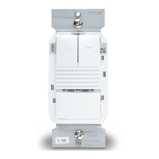
• The PW-311 has one relay with
dimming control capability and
two buttons to allow control of the
dimming.
• PW sensors contain a light level
sensor. If adequate daylight is
present, the sensor holds the load
OFF until light levels drop, even if
the area is occupied. See the Light
Level Adjustment section.
OPTIONAL NEUTRAL WIRING
Wattstopper
Passive Infrared 0–10 Volt Wall Switch Occupancy Sensor (Version 2)
Interrupteur mural 0–10 Volt avec détecteur de mouvement à infrarouges passif (v2)
Sensor de ocupación con interruptor de pared y tecnología de infrarrojo pasivo de
voltaje 0 a 10 (v2)
Installation Instructions • Instructions d'Installation • Instrucciones de Instalación
Voltages:
PW-311 ....................................................120/277 VAC, 50/60 Hz
PW-311-347 ....................................................347 VAC, 50/60 Hz
Load Limits:
@120 VAC ........... 1000-W tungsten ballast, E-ballast, LED, 1/4 HP
@277 VAC ...................... 1200-W ballast, E-ballast, LED, 1/4 HP
@347 VAC ........................................1500W ballast, LED, 1/4 HP
Time Delay Adjustment ..................................................3 to 30 minutes
Walk-Through Mode ....................... 3 minutes if no activity after 30 sec.
Test Mode ............................................. 10 min. with 10-sec. time delay
PIR Adjustment .................................................................... High or Low
Light Level Adjustment .......................................................8fc to 180+fc
Alerts ........................................................Selectable Audible & Visual
Optional Neutral .....................................................................All models
Multi-Way Capability ...............................................................All models
Terminal screw torque ............................................ 16 lbf-in (18 kgf-cm)
High Trim .................................................................................. 6 to 10 V
Low Trim ..................................................................................... 0 to 4 V
Ramp Up ....................................................................... 1 to 10 seconds
Fade Down ................................................................. 2.5 to 30 seconds
INSTALLATION
#12 – #14 AWG
Cu Wire Only
Red
Black
Breakaway
tab
®
SPECIFICATIONS
WARNING: TURN THE POWER OFF AT THE
CIRCUIT BREAKER BEFORE WIRING.
PW-311 and PW-311-347 Wiring
Strip Gage
Yellow
1/2"
12.7mm
Black
Line
Green
Ground
Neutral
8" flying leads for
line, load, ground
and multi-way
connections
Grey
Violet
Yellow
Optional neutral
terminals behind
Green
breakaway tab
0 a 10V
Dimming
Violet
Driver
Gray
or Ballast
Red
White
(optional)
Tabla de contenido

Manuales relacionados para LEGRAND Wattstopper


Resumen de contenidos para LEGRAND Wattstopper
-
Página 11: Descripción De La Unidad
PLAQUES Les interrupteurs muraux de la série PW de WattStopper peuvent être montés derrière des plaques d’interrupteur standard de style Decorator. Les plaques ne sont pas inclus. Les unités sont disponibles dans les couleurs suivantes, indiquées par le suffixe final du numéro de référence (montré ici entre parenthèses):... -
Página 12: Cableado Neutral Opcional
CABLEADO NEUTRAL OPCIONAL Para las aplicaciones que requieren cableado neutral, remueva la lengüeta como se muestra para exponer las terminales para el cableado. Conductores volantes de 8" por línea, conexiones de carga, tierra y de múltiples vías Gris Violeta Rojo Negro Amarillo Terminales neutras... -
Página 13: Ajuste Del Sensor Y Acceso A Otras Funciones
AJUSTE DEL SENSOR Y ACCESO A OTRAS FUNCIONES Elimine la placa de la pared. Quite la tapa del botón apretando firmemente Botón de aumento los laterales superiores del botón de ensamble. Con cuidado, retírela de la Botón de atenuación unidad. Cuando se completen los ajustes, vuelva a colocar la tapa del botón insertando sus bisagras en las pestañas de la unidad principal y, luego, apriete la parte superior del botón mientras lo presiona hacia la unidad. - Página 14 Recorrido El modo de recorrido acorta el tiempo de demora para reducir la cantidad de tiempo en que la carga está encendida después de un breve momento de ocupación como, por ejemplo, volver a la oficina para buscar algo que se olvidó y salir inmediatamente. Si el modo de recorrido se enciende, el sensor PW apaga la carga tres minutos después de que el área esté...
-
Página 15: Configuración Del Conmutador Selector Para Bascular
Modo de presentación / Modo de desactivación de presentación El modo de Presentación es una función del modo de Encendido automático. Cuando el relé se apaga manualmente, el PW mantiene las luces apagadas hasta que no se detecta ningún movimiento durante el tiempo de demora. Con la ocupación subsiguiente, el PW enciende la carga. -
Página 16: Placas De La Cubierta
2. Si el problema persiste, llame al soporte técnico. PLACAS DE LA CUBIERTA Los interruptores de pared serie PW de WattStopper se encajan detrás de las placas de cubierta de los interruptores con estilo de decoración estándares de la industria. No se incluyen las placas de la cubierta.